AS Level 9618 · Paper 1 · 3.2
Logic Gates and Logic Circuits
The six logic gates, and how to build and describe circuits from them. Read the notes, try the past-paper questions, then check the mark scheme.
Past papers from June 2021 to June 202631 questions · 130 marks
In this subtopic
- NOT, AND, OR, NAND, NOR and XOR: symbols, functions and truth tables
- Drawing a logic circuit from an expression, a truth table or a problem
- Writing a truth table and a logic expression for a circuit
3.2 · 1 of 21Book pages Contents
Logic gates
A logic gate is a basic building block of a digital circuit. Each gate has one or more inputs and produces a single output that depends on its input or inputs. Many logic gates can be joined together to make complex circuits that carry out processing.
Each logic gate has a symbol, which is used in circuit diagrams, and its own truth table, which shows the output for every possible combination of inputs.
You can think of the inputs to a logic gate as 1s and 0s. These values come from the voltage in the circuit: a high voltage counts as 1 (True) and a low voltage counts as 0 (False). The output is usually labelled Q.
Note In Paper 1, logic expressions are written with the words AND, OR, NOT, NAND, NOR and XOR, for example X = (A AND B) OR NOT C. Some books also use the Boolean algebra symbols: A . B for AND, A + B for OR, A ⊕ B for XOR, and a bar over a letter for NOT. These notes use the words.
A logic expression (also called a Boolean expression) describes, with letters for the inputs and these operators, which combinations of inputs give an output of 1.
Used later in
3.2 · 2 of 21Book page Contents
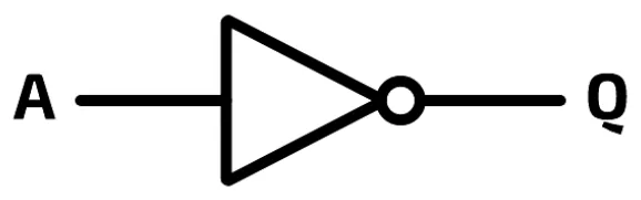
The NOT gate
Builds on
The NOT gate takes a single input and flips it to its logical opposite:
- if the input is 1 (True), the output is 0 (False)
- if the input is 0 (False), the output is 1 (True).
| Input A | Output Q |
|---|---|
| 0 | 1 |
| 1 | 0 |
The logic expression for this gate is Q = NOT A. In symbols it is written as A with a bar over it.
3.2 · 3 of 21Book page Contents
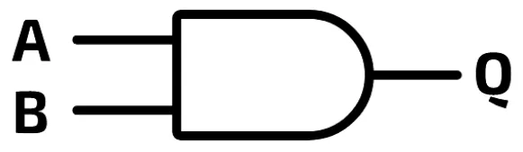
The AND gate
Builds on
The AND gate takes two inputs and gives an output of 1 (True) only if both inputs are 1 (True). This is what you would expect: if you asked for fish and chips and did not get both, you would be disappointed.
| Input A | Input B | Output Q |
|---|---|---|
| 0 | 0 | 0 |
| 0 | 1 | 0 |
| 1 | 0 | 0 |
| 1 | 1 | 1 |
The logic expression for this gate is Q = A AND B. In symbols it is written Q = A . B, where the dot means AND.
Used later in
3.2 · 4 of 21Book page Contents
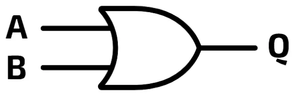
The OR gate
Builds on
The OR gate takes two inputs and gives an output of 1 (True) if either one of the inputs is 1 (True), or both are.
| Input A | Input B | Output Q |
|---|---|---|
| 0 | 0 | 0 |
| 0 | 1 | 1 |
| 1 | 0 | 1 |
| 1 | 1 | 1 |
The logic expression for this gate is Q = A OR B. In symbols it is written Q = A + B, where the plus sign means OR.
3.2 · 5 of 21Book page Contents
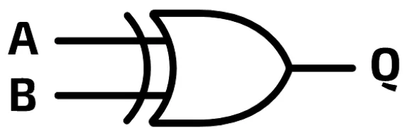
The XOR gate
Builds on
The XOR gate takes two inputs and gives an output of 1 (True) if either input is 1 (True), but not both. Its name is short for exclusive OR, and it is sometimes called EOR. Put another way, the output is 1 only when the two inputs are different.
| Input A | Input B | Output Q |
|---|---|---|
| 0 | 0 | 0 |
| 0 | 1 | 1 |
| 1 | 0 | 1 |
| 1 | 1 | 0 |
The logic expression for this gate is Q = A XOR B. In symbols it is written Q = A ⊕ B, where ⊕ means XOR.
Practise this: past-paper questions
Used later in
3.2 · 6 of 21Book page Contents
The NAND gate
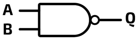
The NAND gate (NOT AND) combines the logic of an AND gate and a NOT gate: it gives the opposite of the output of an AND gate. So its output is 0 only when both inputs are 1.
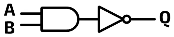
The symbol for a NAND gate combines the symbols for the two gates: the AND shape, with the small circle from the NOT gate on its output.
| Input A | Input B | Output Q |
|---|---|---|
| 0 | 0 | 1 |
| 0 | 1 | 1 |
| 1 | 0 | 1 |
| 1 | 1 | 0 |
The logic expression for this gate is Q = A NAND B, which is the same as Q = NOT (A AND B).
Practise this: past-paper questions
3.2 · 7 of 21Book page Contents
The NOR gate
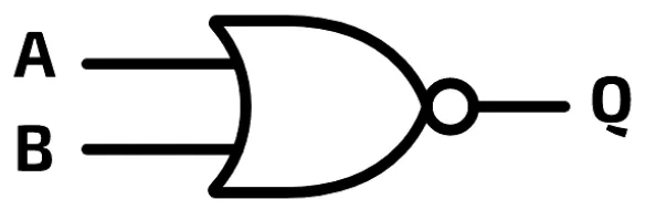
The NOR gate (NOT OR) combines the logic of an OR gate and a NOT gate: it gives the opposite of the output of an OR gate. So its output is 1 only when both inputs are 0.
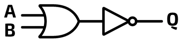
The symbol for a NOR gate combines the symbols for the two gates: the OR shape, with the small circle from the NOT gate on its output.
| Input A | Input B | Output Q |
|---|---|---|
| 0 | 0 | 1 |
| 0 | 1 | 0 |
| 1 | 0 | 0 |
| 1 | 1 | 0 |
The logic expression for this gate is Q = A NOR B, which is the same as Q = NOT (A OR B).
Practise this: past-paper questions
Used later in
3.2 · 8 of 21Contents
The six gates side by side
Builds on
This table puts the truth tables of the five two-input gates together, so you can compare them:
| A | B | AND | OR | XOR | NAND | NOR |
|---|---|---|---|---|---|---|
| 0 | 0 | 0 | 0 | 0 | 1 | 1 |
| 0 | 1 | 0 | 1 | 1 | 1 | 0 |
| 1 | 0 | 0 | 1 | 1 | 1 | 0 |
| 1 | 1 | 1 | 1 | 0 | 0 | 0 |
What each gate does
- NOT gate: the output is the opposite of the single input.
- AND gate: the output is 1 only when both inputs are 1.
- OR gate: the output is 1 when either input is 1, or both are.
- XOR gate: the output is 1 only when the two inputs are different.
- NAND gate: the output is 0 only when both inputs are 1 (the opposite of AND).
- NOR gate: the output is 1 only when both inputs are 0 (the opposite of OR).
In Paper 1, every gate except the NOT gate has exactly two inputs. So an expression such as A AND B AND C is drawn with two AND gates: the first works out A AND B, and the second ANDs that result with C. In the same way, A OR B OR C needs two OR gates.
Practise this: past-paper questions
- June 2021 · Paper 11 · Q8Tick (✓) one box in each row to identify the logic gate that each statement describes. | Statement | AND | NAND | NOR | XOR | OR | | The output is…
- November 2021 · Paper 11 · Q3(c)Identify one logic gate not used in the given logic circuit. Draw the symbol for the logic gate and complete its truth table. Logic gate: Symbol:…
- November 2021 · Paper 12 · Q2(a)Complete the truth table for each of the following two logic gates. Gate 1: A | B | Output 0 | 0 | 0 | 1 | 1 | 0 | 1 | 1 | Gate 2: A | B | Output…
- June 2022 · Paper 11 · Q2(c)(i)Complete the table by writing one set of values (input 1 and input 2) for each gate that will give the output 1. Gate | Input 1 | Input 2 | Output…
3.2 · 9 of 21Book pages Contents
A simple logic circuit
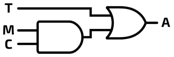
A digital electronic circuit in a computer system is usually made up of millions of logic gates, and each circuit is designed to carry out a particular job. A logic circuit is a set of logic gates joined together to produce outputs from inputs. Real circuits can be very complex, so the ideas are shown here with a control circuit made of just a few gates.
This circuit controls an alarm. The alarm sounds if motion is detected and it is between 20:00 and 06:00. It also sounds if the temperature goes above 30 °C, whatever the time.
The circuit has three inputs, labelled T, M and C:
- The temperature sensor (T) gives 1 if the temperature is over 30 °C, otherwise 0.
- The motion sensor (M) gives 1 if motion is detected, otherwise 0.
- The clock (C) gives 1 if the time is between 20:00 and 06:00, otherwise 0.
There is one output: the alarm (A), which sounds if it receives a 1 and stays silent otherwise.
3.2 · 10 of 21Book pages Contents
The circuit’s truth table and logic expression
Builds on
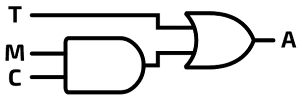
A whole circuit also has a truth table. It shows every possible combination of inputs together with the output each one gives. Remember: T is temperature, M is motion, C is the clock and A is the alarm.
| T | M | C | A |
|---|---|---|---|
| 0 | 0 | 0 | 0 |
| 0 | 0 | 1 | 0 |
| 0 | 1 | 0 | 0 |
| 0 | 1 | 1 | 1 |
| 1 | 0 | 0 | 1 |
| 1 | 0 | 1 | 1 |
| 1 | 1 | 0 | 1 |
| 1 | 1 | 1 | 1 |
There are eight possible combinations of inputs, and five of them make the alarm sound: the rows where A is 1. They are:
- whenever T is 1 (the temperature is above 30 °C)
- whenever M is 1 (the motion sensor detects movement) and C is 1 (the time is between 20:00 and 06:00).
Every logic circuit can also be written as a logic expression. A logic expression describes the combinations of inputs that give an output of 1. From the truth table, that happens when T is 1, or when M is 1 and C is 1. So the expression for the circuit is:
A = (M AND C) OR TIn symbols this is A = (M . C) + T.
Notice that you do not write (M = 1 AND C = 1) OR T = 1. The "= 1" is understood: a letter on its own in an expression means that input is 1. To say an input must be 0, write NOT in front of it. For example, A = M AND NOT C means the output is 1 when M is 1 and C is 0.
3.2 · 11 of 21Book page Contents
How many rows in a truth table
Builds on
Each input can only be 1 or 0. So a circuit with 2 inputs has 22 = 4 possible combinations of inputs, and its truth table has 4 rows. With 3 inputs there are 23 = 8 combinations. In general, n inputs give 2n combinations.
To make a truth table for a circuit with 3 inputs, A, B and C, first work out how many rows you need: 23 = 8. Then draw a column for each input, with 8 rows. Fill in the inputs by counting up in binary from 000 to 111: column C goes 0, 1, 0, 1, ..., column B goes in pairs 0, 0, 1, 1, ..., and column A is four 0s then four 1s. This way no combination is missed or repeated.
| A | B | C |
|---|---|---|
| 0 | 0 | 0 |
| 0 | 0 | 1 |
| 0 | 1 | 0 |
| 0 | 1 | 1 |
| 1 | 0 | 0 |
| 1 | 0 | 1 |
| 1 | 1 | 0 |
| 1 | 1 | 1 |
3.2 · 12 of 21Book pages Contents
A truth table from a circuit diagram
When you are given a circuit diagram, break down the logic of each gate in the circuit. Take this circuit:
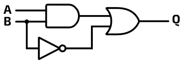
- The truth table needs 4 rows, because there are 2 inputs (A and B): 22 = 4.
- The truth table needs 5 columns: 2 for the inputs (A and B) and 3 for the logic gates in the diagram (AND, OR and NOT).
Before you fill in the truth table, work out the expression for the output of each gate. For example, the AND gate has inputs A and B, so its output is A AND B. Keep track of each gate’s output by writing it on the line in the circuit diagram. Do not try to keep it all in your head, or you may make a mistake. Here is the diagram with the output of each gate written on it:
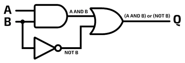
Now use these expressions as column headings. The final output is called Q.
| A | B | A AND B | NOT B | Q = (A AND B) OR (NOT B) |
|---|---|---|---|---|
| 0 | 0 | 0 | 1 | 1 |
| 0 | 1 | 0 | 0 | 0 |
| 1 | 0 | 0 | 1 | 1 |
| 1 | 1 | 1 | 0 | 1 |
Practise this: past-paper questions
- November 2021 · Paper 11 · Q3(b)Complete the truth table for the given logic circuit. | A | B | C | Working space | X | | 0 | 0 | 0 | | | | 0 | 0 | 1 | | | | 0 | 1 | 0 | | | | 0…
- June 2023 · Paper 13 · Q1(b)Complete the truth table for this logic circuit: A | B | C | Working space | X 0 | 0 | 0 | | 0 | 0 | 1 | | 0 | 1 | 0 | | 0 | 1 | 1 | | 1 | 0 | 0 |…
- June 2025 · Paper 11 · Q1(b)Complete the truth table for the following logic circuit. A | B | C | Working space | X 0 | 0 | 0 | | 0 | 0 | 1 | | 0 | 1 | 0 | | 0 | 1 | 1 | | 1…
- June 2026 · Paper 12 · Q8(a)Complete the truth table for the given logic circuit. X A Y B Z X | Y | Z | working space | A | B 0 | 0 | 0 0 | 0 | 1 0 | 1 | 0 0 | 1 | 1 1 | 0 |…
3.2 · 13 of 21Book pages Contents
A truth table from a logic expression
Take this logic expression:
Q = (A OR B) AND (NOT C AND A)- The truth table needs 8 rows, because there are 3 inputs (A, B and C): 23 = 8.
- The truth table needs 7 columns: 3 for the inputs and 4 for the operators in the expression (two ANDs, one OR and one NOT).
Start by drawing the table. Put the inputs in the first columns, on the left.
Next, there are two parts of the expression in brackets. These must be worked out first, before the AND that joins them. It does not matter which bracket you do first. A OR B is straightforward. However, before you can work out NOT C AND A, you must work out NOT C.
Finally, work out the AND that joins the two brackets. This table shows the operations in a logical order:
| A | B | C | A OR B | NOT C | NOT C AND A | Q |
|---|---|---|---|---|---|---|
| 0 | 0 | 0 | 0 | 1 | 0 | 0 |
| 0 | 0 | 1 | 0 | 0 | 0 | 0 |
| 0 | 1 | 0 | 1 | 1 | 0 | 0 |
| 0 | 1 | 1 | 1 | 0 | 0 | 0 |
| 1 | 0 | 0 | 1 | 1 | 1 | 1 |
| 1 | 0 | 1 | 1 | 0 | 0 | 0 |
| 1 | 1 | 0 | 1 | 1 | 1 | 1 |
| 1 | 1 | 1 | 1 | 0 | 0 | 0 |
Look at the last two columns: they are identical. This is an example of spotting, from the truth table, that an expression can be simplified. A simpler expression can carry out the same logic as a more complex one. Here, NOT C AND A gives the same output as (A OR B) AND (NOT C AND A).
Practise this: past-paper questions
- June 2021 · Paper 12 · Q3(b)Complete the truth table for the logic expression: S = (A AND B AND C) OR (B XOR C) | A | B | C | Working space | S | | 0 | 0 | 0 | | | | 0 | 0 |…
- June 2022 · Paper 12 · Q7Complete the truth table for the following logic expression: X = (A XOR B) AND NOT C A | B | C | Working space | X 0 | 0 | 0 | | 0 | 0 | 1 | | 0 |…
- June 2022 · Paper 13 · Q7(b)Complete the truth table for the following logic expression: X = (A NAND B) OR (A AND NOT C) | A | B | C | Working space | X | | 0 | 0 | 0 | | | |…
- November 2022 · Paper 11 · Q3(b)Complete the truth table for the logic expression: X = NOT ((NOT A AND NOT B) OR (NOT B AND NOT C)) | A | B | C | Working space | X | | 0 | 0 | 0…
Show 11 more
- November 2022 · Paper 12 · Q3(b)Complete the truth table for the logic expression: X = NOT (A OR B OR C) AND (B NOR C) | A | B | C | Working space | X | | 0 | 0 | 0 | | | | 0 | 0…
- November 2022 · Paper 13 · Q5(b)Complete the truth table for the logic expression: Y = (NOT P AND Q) OR (Q AND NOT R) | P | Q | R | Working space | Y | | 0 | 0 | 0 | | | | 0 | 0…
- June 2023 · Paper 12 · Q6(b)Complete the truth table for this logic expression: Z = (NOT P OR Q) XOR (R NOR Q) | P | Q | R | Working space | Z | | 0 | 0 | 0 | | | | 0 | 0 | 1…
- November 2023 · Paper 11 · Q4(a)Complete the truth table for the logic expression: X = NOT (A NAND B) XOR (NOT B AND (B NOR C)) A | B | C | Working space | X 0 | 0 | 0 | | 0 | 0…
- November 2023 · Paper 12 · Q4(b)Complete the truth table for the logic expression: X = A XOR (B AND (A NAND B) AND NOT C) A | B | C | Working space | X 0 | 0 | 0 | | 0 | 0 | 1 |…
- November 2023 · Paper 13 · Q4(a)Complete the truth table for the logic expression: Y = ((P AND Q) XOR ((NOT Q) OR R)) AND NOT P P | Q | R | Working space | Y 0 | 0 | 0 | | 0 | 0…
- November 2024 · Paper 12 · Q1(a)Complete the truth table for the logic expression: X = (A XOR B) NAND (A AND (B XOR C)) | A | B | C | Working space | X | | 0 | 0 | 0 | | | | 0 |…
- June 2025 · Paper 12 · Q4(b)Complete the truth table for the logic expression: X = NOT (A AND (B XOR C)) A | B | C | Working space | X 0 | 0 | 0 | | 0 | 0 | 1 | | 0 | 1 | 0 |…
- June 2025 · Paper 13 · Q4(b)Complete the truth table for the logic expression: X = (A OR B) XOR (B OR C) XOR (NOT A NAND C) A | B | C | Working space | X 0 | 0 | 0 | | 0 | 0…
- November 2025 · Paper 12 · Q9(b)Consider the following logic expression: X = NOT ((A NAND B) XOR (NOT A OR NOT C)) A truth table for the logic expression is given: Row number | A…
- November 2025 · Paper 13 · Q3(a)Complete the truth table for the following logic expression: X = (A NOR B) NAND (C XOR B) A | B | C | Working space | X 0 | 0 | 0 | | 0 | 0 | 1 |…
3.2 · 14 of 21Book pages Contents
A logic expression from a circuit diagram
Builds on
Circuit diagrams, truth tables and problem statements can all be written as a logic expression. From any one of them you can work out the logic expression, and the other way round: from an expression you can make a truth table or a circuit diagram, or even write a problem statement.
Take this circuit diagram:
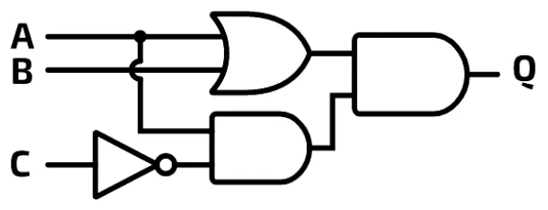
Take each gate in turn, working from left to right, and write an expression for that part of the circuit on its output line.
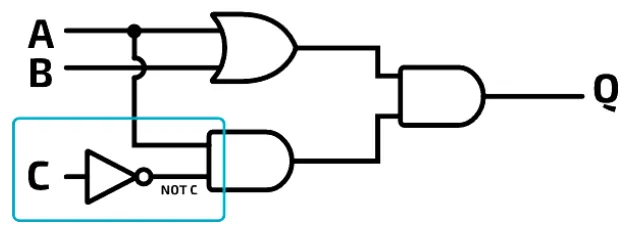
The NOT gate (blue box). The input is C, so the output is NOT C. Write NOT C on the output line.
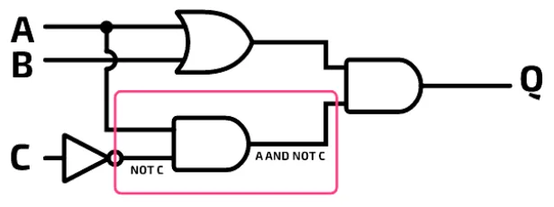
The first AND gate (pink box). One input is A and the other is NOT C, so the output is A AND NOT C. Write A AND NOT C on the output line.
The OR gate (yellow box). One input is A and the other is B, so the output is A OR B. Write A OR B on the output line.
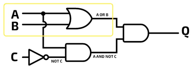
The second AND gate (purple box). One input is A OR B and the other is A AND NOT C, so the output is (A OR B) AND (A AND NOT C). Write this on the output line.
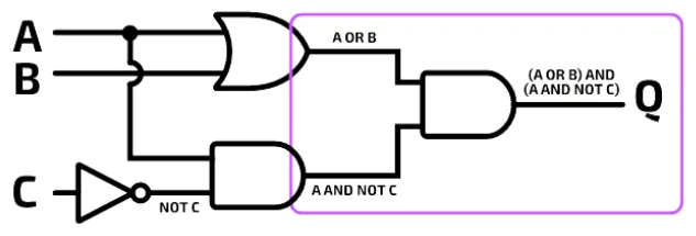
This final output is the expression for the whole circuit:
Q = (A OR B) AND (A AND NOT C)- You do not actually need the brackets around A AND NOT C, but they do no harm and make the expression easier to read.
- Breaking the expression up like this is also useful when you need to draw a truth table for part of a circuit.
Practise this: past-paper questions
- November 2021 · Paper 11 · Q3(a)Write the logic expression for the logic circuit
- June 2022 · Paper 11 · Q2(c)(ii)Write the logic expression for the given logic circuit
- June 2022 · Paper 13 · Q7(a)Write the logic expression for the following logic circuit
- November 2023 · Paper 12 · Q4(a)Write the Boolean expression that corresponds to the following logic circuit
Show 6 more
- November 2024 · Paper 13 · Q1(b)Write the logic expression for the following logic circuit. X
- June 2025 · Paper 11 · Q1(a)Write the logic expressions for the following logic circuit. X = Y
- June 2025 · Paper 12 · Q4(a)Write the logic expressions for the following logic circuit. X = Y
- June 2025 · Paper 13 · Q4(a)Write the logic expressions for the following logic circuit. X = Y
- November 2025 · Paper 12 · Q9(a)Consider the following logic circuit: [logic circuit diagram with inputs A, B, C and output X] Write the logic expression for the logic circuit.…
- June 2026 · Paper 11 · Q6(a)Write the logic expressions for the following logic circuit. B Y C D Z E Y = Z
3.2 · 15 of 21Book pages Contents
A logic expression from a problem statement
Builds on
A problem statement describes in words when a system should switch something on. Take this one:
Sam and Zac live in a house with a smart heating system. The system turns the heating on if either of them is at home and the temperature drops below 18 °C. The smart system can be switched off completely with an override button.
- A temperature sensor returns 1 if the temperature drops below 18 °C, and 0 otherwise.
- Sam’s and Zac’s mobile phones connect to the WiFi when they are at home, and the system can sense this: 1 means the phone is connected to the WiFi, 0 means it is not.
- The override button returns 1 if the system is switched off, and 0 otherwise.
- The heating is switched on and off by an actuator. When the actuator is 1, the heating is on.
Worked example
Write a logic expression for the smart heating system.
- Step 1Identify and label the inputs. There are four: the temperature sensor (T), the sensor for Sam’s phone (S), the sensor for Zac’s phone (Z) and the override button (B).
- Step 2Identify and label the output: the actuator (H).
- Step 3Break down the logic. The heating turns on if the override button (B) is not switched on, AND Sam is home (S) OR Zac is home (Z), AND the temperature is below 18 °C (T).
- Step 4Write the logic using only the letters: NOT B, AND, S OR Z AND T. The last part needs brackets. The logic is (S OR Z) AND T. Without the brackets, the order of precedence would make it S OR (Z AND T), which is wrong.
- Step 5Write the final expression: H = (NOT B) AND ((S OR Z) AND T).
In Boolean algebra symbols, the same expression is written with . for AND, + for OR and a bar over B for NOT B.
Once you have the expression, you can build the logic circuit and the truth table from it in the usual way. For the heating system the circuit needs four gates: a NOT gate on B, an OR gate for S and Z, an AND gate that joins the OR output with T, and a final AND gate that joins NOT B with that result to give H. With four inputs, its truth table would have 24 = 16 rows.
From a problem statement to an expression, circuit or truth table
- Identify and label the inputs and the output.
- Break the statement down into conditions joined by AND, OR and NOT.
- Add brackets so each part is worked out in the right order.
- Write the expression, then draw the circuit or complete the truth table from it.
Practise this: past-paper questions
- November 2022 · Paper 12 · Q3(a)A greenhouse has an automatic window. The window (X) operates according to the following criteria: | Parameter | Description of parameter | Binary…
- November 2024 · Paper 11 · Q5(b)The floodlight (X) and audio alarm (Y) operate according to the following criteria: | Parameter | Description of parameter | Binary value |…
3.2 · 16 of 21Book page Contents
A logic expression from a simple truth table
Sometimes you are given a truth table and asked to write the logic expression. Take this one:
| A | B | Q |
|---|---|---|
| 0 | 0 | 1 |
| 0 | 1 | 1 |
| 1 | 0 | 0 |
| 1 | 1 | 1 |
First check whether the table matches the truth table of one of the two-input gates. It is useful to learn the gate truth tables by heart for questions like this. This table does not match any of them.
Next, look only at the rows with an output of 1, because an expression describes the combinations of inputs that give an output of 1. This is very important: you do not need to worry about the 0s.
In this table, the output is 1:
- whenever A is 0: this logic is NOT A
- or whenever B is 1: this logic is B.
So the expression is:
Q = NOT A OR BPractise this: past-paper questions
- June 2023 · Paper 13 · Q1(a)Write the logic expression for this truth table: A | B | C | X 0 | 0 | 0 | 1 0 | 0 | 1 | 1 0 | 1 | 0 | 0 0 | 1 | 1 | 0 1 | 0 | 0 | 1 1 | 0 | 1 | 1…
- June 2024 · Paper 11 · Q1(a)Tick (✓) one box to identify the correct logic statement for this truth table. A | B | C | X 0 | 0 | 0 | 1 0 | 0 | 1 | 0 0 | 1 | 0 | 0 0 | 1 | 1 |…
- June 2024 · Paper 13 · Q6Each of the following truth tables has three inputs (A, B and C) and one output (X). Draw one line to match each truth table with its logic…
- November 2025 · Paper 11 · Q3(b)Write the logic expression for the following truth table. R | S | T | Q 0 | 0 | 0 | 0 0 | 0 | 1 | 1 0 | 1 | 0 | 0 0 | 1 | 1 | 0 1 | 0 | 0 | 0 1 |…
3.2 · 17 of 21Book pages Contents
A logic expression from a harder truth table
Now take a truth table with three inputs. The rows are numbered so they can be talked about:
| Row | A | B | C | Q |
|---|---|---|---|---|
| 1 | 0 | 0 | 0 | 0 |
| 2 | 0 | 0 | 1 | 0 |
| 3 | 0 | 1 | 0 | 1 |
| 4 | 0 | 1 | 1 | 1 |
| 5 | 1 | 0 | 0 | 1 |
| 6 | 1 | 0 | 1 | 0 |
| 7 | 1 | 1 | 0 | 1 |
| 8 | 1 | 1 | 1 | 1 |
Focus on the rows where the output is 1 (rows 3, 4, 5, 7 and 8), and look for a pattern in their inputs.
Worked example
Write the logic expression for this truth table.
- Step 1The output is always 1 when B = 1, so one part of the expression is just B. This covers rows 3, 4, 7 and 8.
- Step 2Row 5 (A = 1, B = 0, C = 0) also gives an output of 1, so the expression will be B OR something, where the something covers row 5.
- Step 3The logic for row 5 on its own is A AND NOT B AND NOT C. But B on its own is already part of the expression, so you can leave out the NOT B: the part you need is A AND NOT C.
- Step 4Check this against the table: row 7 also has A = 1 and C = 0 and gives 1, so B really does not matter for this part.
- Step 5The expression is Q = B OR (A AND NOT C).
If you cannot see a pattern, there is a method that always works. Write one AND term for each row where the output is 1, using NOT for each input that is 0 in that row, and join the terms with OR. For the simple truth table in the last section this gives (NOT A AND NOT B) OR (NOT A AND B) OR (A AND B). It is longer than NOT A OR B, but it is also correct, because it gives exactly the same truth table.
Practise this: past-paper questions
- June 2023 · Paper 13 · Q1(a)Write the logic expression for this truth table: A | B | C | X 0 | 0 | 0 | 1 0 | 0 | 1 | 1 0 | 1 | 0 | 0 0 | 1 | 1 | 0 1 | 0 | 0 | 1 1 | 0 | 1 | 1…
- June 2024 · Paper 11 · Q1(a)Tick (✓) one box to identify the correct logic statement for this truth table. A | B | C | X 0 | 0 | 0 | 1 0 | 0 | 1 | 0 0 | 1 | 0 | 0 0 | 1 | 1 |…
- June 2024 · Paper 13 · Q6Each of the following truth tables has three inputs (A, B and C) and one output (X). Draw one line to match each truth table with its logic…
- November 2025 · Paper 11 · Q3(b)Write the logic expression for the following truth table. R | S | T | Q 0 | 0 | 0 | 0 0 | 0 | 1 | 1 0 | 1 | 0 | 0 0 | 1 | 1 | 0 1 | 0 | 0 | 0 1 |…
3.2 · 18 of 21Book page Contents
Operator precedence
The operators in a logic expression have an order of precedence, which says which operations are worked out first:
- Brackets
- NOT
- AND
- OR
Some gates combine more than one basic logic operation. For example, a NAND gate combines AND and NOT. So you must also know where these extra operators come in the order. Operators on the same line have equal precedence and can be worked out in any order:
- Brackets
- NOT
- AND, NAND
- OR, NOR, XOR
Note You may sometimes see a different order of precedence, especially for XOR. In an exam you should not lose marks if the order of precedence is not completely clear, and exam expressions usually use brackets to make the order clear.
3.2 · 19 of 21Book page Contents
A circuit diagram from a simple expression
Builds on
Think about how you would draw the logic circuit for this expression:
Q = A AND B OR CYou might draw it in one of two ways:
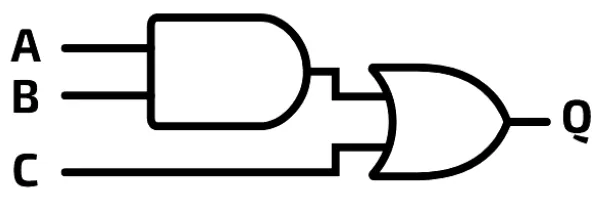
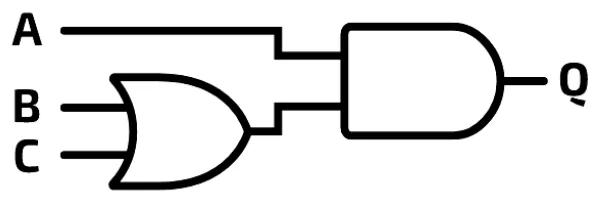
The correct diagram is option A. The order of precedence says AND is worked out before OR, so the AND must be carried out first.
It is very easy to make a mistake with precedence when you are given an expression. It helps to add brackets to remind you of the order: Q = (A AND B) OR C.
The two options are not the same. You can prove this with a truth table for each one: the outputs are different in rows 2 and 4.
| Row | A | B | C | Option A: (A AND B) OR C | Option B: A AND (B OR C) |
|---|---|---|---|---|---|
| 1 | 0 | 0 | 0 | 0 | 0 |
| 2 | 0 | 0 | 1 | 1 | 0 |
| 3 | 0 | 1 | 0 | 0 | 0 |
| 4 | 0 | 1 | 1 | 1 | 0 |
| 5 | 1 | 0 | 0 | 0 | 0 |
| 6 | 1 | 0 | 1 | 1 | 1 |
| 7 | 1 | 1 | 0 | 1 | 1 |
| 8 | 1 | 1 | 1 | 1 | 1 |
3.2 · 20 of 21Book pages Contents
A circuit diagram from a harder expression
Builds on
Now work through a harder example. Here is the expression:
Q = (A OR B) AND (NOT C AND A)Remember the order of precedence: brackets, then NOT, then AND and NAND, then OR, NOR and XOR.
A circuit diagram normally has the inputs on the left and the output or outputs on the right. So start by writing A, B and C on the left of the page and Q on the right.
Before you add any gates, count how many of each gate you need. This expression has two AND operators, one OR operator and one NOT operator, so the diagram needs these four gates.
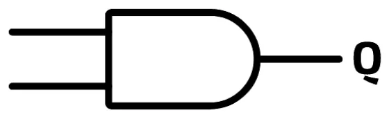
Step 1: the final AND gate. The last operator to be worked out is the one between the two brackets: an AND. Start by drawing an AND gate just before the output Q, and connect its output to Q.
Step 2: the OR gate. Now look at either of the brackets that feed into this AND gate. On the left is (A OR B). This needs an OR gate, so draw it to the left of the AND gate, with inputs A and B, and connect its output to one of the inputs of the AND gate. It does not matter which input you use.
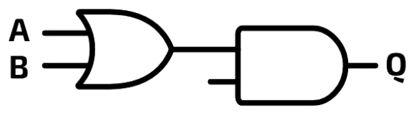
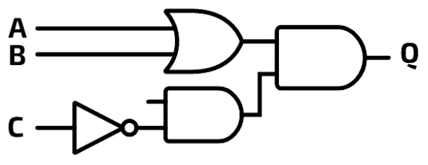
Step 3: the NOT gate and the second AND gate. Now take the bracket on the right: (NOT C AND A). NOT has a higher precedence than AND, so NOT C must happen first. Draw a NOT gate with its input from C, and its output going into one input of a second AND gate. Place this second AND gate between the NOT gate and the final AND gate, and connect its output to the final AND gate.
Step 4: the final connection. Connect the other input of the second AND gate to A. When several gates take the same input, like A here, draw a branch in the line, with a dot to show the join.
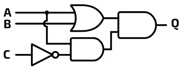
In a busy circuit, lines may cross. Look at the small curve in the branch from A where it crosses the line from B to the OR gate: the curve shows that the two lines are not connected.
Practise this: past-paper questions
- June 2021 · Paper 12 · Q3(a)Draw the logic circuit for the given expression. (Inputs A, B and C are given on the left of the answer space; the output S is on the right.)
- November 2021 · Paper 12 · Q2(b)Draw a logic circuit for the following logic expression. X = NOT(NOT(A AND B)AND C)
- November 2022 · Paper 11 · Q3(a)Draw a logic circuit for the logic expression: X = NOT ((NOT A AND NOT B) OR (NOT B AND NOT C))
- November 2022 · Paper 12 · Q3(a)A greenhouse has an automatic window. The window (X) operates according to the following criteria: | Parameter | Description of parameter | Binary…
Show 11 more
- November 2022 · Paper 13 · Q5(a)Draw a logic circuit for the logic expression: X = NOT ((NOT (A AND B)) OR (NOT (B AND C)))
- June 2023 · Paper 11 · Q5(a)Draw the logic circuit for this logic expression: T = (NOT A OR B) XOR (C NAND D)
- June 2023 · Paper 12 · Q6(a)Draw the logic circuit for this logic expression: Z = (R XOR S) AND (NOT T NOR P)
- November 2023 · Paper 11 · Q4(b)Draw a logic circuit for the logic expression: X = (A AND NOT (B OR C)) AND (B NOR C)
- November 2023 · Paper 13 · Q4(b)Draw a logic circuit for the logic expression: Y = ((P AND Q) XOR ((NOT Q) OR R)) AND NOT P
- June 2024 · Paper 11 · Q1(b)Draw a logic circuit for the logic expression: X = NOT (NOT A AND (NOT B XOR C))
- June 2024 · Paper 12 · Q1(b)Draw a logic circuit for this logic expression: X = NOT ((A AND B) OR (C AND D))
- November 2024 · Paper 12 · Q1(b)Draw the logic circuit for the logic expression: W = P NAND ((Q OR NOT R) XOR (P XOR Q)) P Q W R
- November 2024 · Paper 13 · Q1(c)Draw the logic circuit for the logic expression: X = ((NOT A AND (B AND C)) OR (B NAND C)) AND NOT A
- November 2025 · Paper 11 · Q3(a)Draw a logic circuit for the logic expression: X = NOT ((A NAND B) XOR (NOT A OR NOT C))
- November 2025 · Paper 13 · Q3(b)Draw a logic circuit for the logic expression: X = NOT (((A AND B) OR C) AND (C NOR D)) [drawing area with inputs A, B, C, D on the left and…
3.2 · 21 of 21Book pages Contents
A circuit diagram from a truth table
To draw a circuit diagram from a truth table, you need to write the logic expression first. Take this truth table:
| A | B | C | Q |
|---|---|---|---|
| 0 | 0 | 0 | 0 |
| 0 | 0 | 1 | 0 |
| 0 | 1 | 0 | 0 |
| 0 | 1 | 1 | 0 |
| 1 | 0 | 0 | 0 |
| 1 | 0 | 1 | 1 |
| 1 | 1 | 0 | 1 |
| 1 | 1 | 1 | 1 |
Here, Q is 1 when A is 1 AND (B is 1 OR C is 1). So the expression for the truth table is:
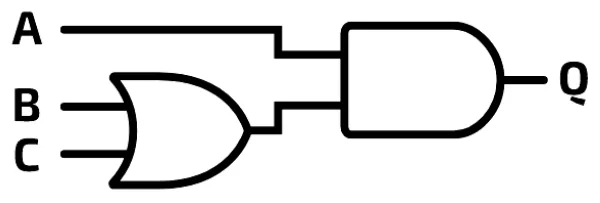
Q = A AND (B OR C)Now draw the circuit diagram from the expression in the usual way: an OR gate for B OR C, and an AND gate that joins A with the output of the OR gate.
3.2
Concepts in 3.2
Every idea explained in 3.2, and where else in the notes it is used.
Zain Merchant's notes, page by page, as printed in his book. The Notes tab has the same notes as text, with links.
Past-paper questions and mark schemes © Cambridge University Press & Assessment. Compiled for revision by Zain Merchant.
- June 2021 · Paper 11 · Q8Notes:The six gates side by side
- June 2021 · Paper 12 · Q3Notes:A truth table from a logic expressionA circuit diagram from a harder expression
- November 2021 · Paper 11 · Q3Notes:The six gates side by sideA truth table from a circuit diagramA logic expression from a circuit diagram
- November 2021 · Paper 12 · Q2Notes:The six gates side by sideA circuit diagram from a harder expression
- June 2022 · Paper 11 · Q2Notes:The six gates side by sideA logic expression from a circuit diagram
- June 2022 · Paper 12 · Q7Notes:A truth table from a logic expression
- June 2022 · Paper 13 · Q7Notes:A truth table from a logic expressionA logic expression from a circuit diagram
- November 2022 · Paper 11 · Q3Notes:A truth table from a logic expressionA circuit diagram from a harder expression
- November 2022 · Paper 12 · Q3Notes:A truth table from a logic expressionA logic expression from a problem statementA circuit diagram from a harder expression
- November 2022 · Paper 13 · Q5Notes:A truth table from a logic expressionA circuit diagram from a harder expression
- June 2023 · Paper 11 · Q5Notes:The NAND gateThe NOR gateA circuit diagram from a harder expression
- June 2023 · Paper 12 · Q6Notes:A truth table from a logic expressionA circuit diagram from a harder expression
- June 2023 · Paper 13 · Q1Notes:A truth table from a circuit diagramA logic expression from a simple truth tableA logic expression from a harder truth table
- November 2023 · Paper 11 · Q4Notes:A truth table from a logic expressionA circuit diagram from a harder expression
- November 2023 · Paper 12 · Q4Notes:A truth table from a logic expressionA logic expression from a circuit diagram
- November 2023 · Paper 13 · Q4Notes:A truth table from a logic expressionA circuit diagram from a harder expression
- June 2024 · Paper 11 · Q1Notes:A logic expression from a simple truth tableA logic expression from a harder truth tableA circuit diagram from a harder expression
- June 2024 · Paper 12 · Q1Notes:The six gates side by sideA circuit diagram from a harder expression
- June 2024 · Paper 13 · Q6Notes:A logic expression from a simple truth tableA logic expression from a harder truth table
- November 2024 · Paper 11 · Q5Notes:A logic expression from a problem statement
- November 2024 · Paper 12 · Q1Notes:A truth table from a logic expressionA circuit diagram from a harder expression
- November 2024 · Paper 13 · Q1Notes:The XOR gateA logic expression from a circuit diagramA circuit diagram from a harder expression
- June 2025 · Paper 11 · Q1Notes:A truth table from a circuit diagramA logic expression from a circuit diagram
- June 2025 · Paper 12 · Q4Notes:A truth table from a logic expressionA logic expression from a circuit diagram
- June 2025 · Paper 13 · Q4Notes:A truth table from a logic expressionA logic expression from a circuit diagram
- November 2025 · Paper 11 · Q3Notes:A logic expression from a simple truth tableA logic expression from a harder truth tableA circuit diagram from a harder expression
- November 2025 · Paper 12 · Q9Notes:A truth table from a logic expressionA logic expression from a circuit diagram
- November 2025 · Paper 13 · Q3Notes:A truth table from a logic expressionA circuit diagram from a harder expression
- June 2026 · Paper 11 · Q6Notes:The NAND gateA logic expression from a circuit diagram
- June 2026 · Paper 12 · Q8Notes:A truth table from a circuit diagramA logic expression from a simple truth tableA logic expression from a harder truth table
- June 2026 · Paper 13 · Q2Notes:The six gates side by sideA truth table from a circuit diagram
Past-paper questions and mark schemes © Cambridge University Press & Assessment. Compiled for revision by Zain Merchant.
Try the questions first.
Write your answers, then check them against the mark scheme. Your choice is remembered on this device.