A Level 9618 · Paper 3 · 15.2
Boolean Algebra and Logic Circuits
Circuits that add and remember, and the algebra that makes circuits simpler. Read the notes, try the past-paper questions, then check the mark scheme.
Past papers from June 2021 to June 202622 questions · 180 marks
In this subtopic
- Truth tables for logic circuits, half adders and full adders
- SR and JK flip-flops, and how they store data
- Boolean algebra and De Morgan's laws
- Karnaugh maps, and why they help
15.2 · 1 of 21Book pages Contents
The half adder
Builds on
A processor can only carry out a very small number of different operations on binary data, and you will start to see this when you solve problems in assembly language. These operations are just combinations of three basic operations: adding, shifting and flipping. If you understand how adding works, you will properly understand what happens in a computer’s Arithmetic and Logic Unit (ALU).
A binary half adder is a circuit that adds two single-bit binary numbers together. The possible calculations are:
- 0 + 0 = 0
- 0 + 1 = 1
- 1 + 0 = 1
- 1 + 1 = 10
The last calculation is the interesting one: its answer cannot be stored in a single bit. The result of 1 + 1 is 0 carry 1.
Now put this into a truth table with two inputs and two outputs. The inputs, A and B, are the two bits being added. The outputs are S and C: S is the sum (the result of the addition as a single bit) and C is the carry bit.
| Input A | Input B | Carry C | Sum S |
|---|---|---|---|
| 0 | 0 | 0 | 0 |
| 0 | 1 | 0 | 1 |
| 1 | 0 | 0 | 1 |
| 1 | 1 | 1 | 0 |
The carry column is produced by the logic A AND B, and the sum column is produced by the logic A XOR B. Using this, you can build the circuit that takes two single-bit numbers and adds them together: an XOR gate gives the sum and an AND gate gives the carry. This circuit is the binary half adder.
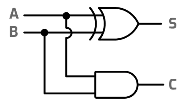
The two outputs of a half adder
- S (sum): the result of adding the two bits, as a single bit. S = A XOR B.
- C (carry): the bit carried to the next column. C = A AND B.
Practise this: past-paper questions
- June 2022 · Paper 32 · Q6(a)Complete the truth table for this logic circuit. | INPUT | | OUTPUT | | | A | B | E | F | | 0 | 0 | | | | 0 | 1 | | | | 1 | 0 | | | | 1 | 1 | | |
- June 2022 · Paper 32 · Q6(b)(i)State the name of this logic circuit
- June 2022 · Paper 32 · Q6(b)(ii)State the purpose of each output E and F. Purpose of E Purpose of F
15.2 · 2 of 21Book pages Contents
The full adder
A half adder can only add two single-bit numbers. To add bigger numbers, a more complicated circuit is needed. Think about adding 101 + 111 in binary (5 + 7 in denary).
Worked example
Add the binary numbers 101 and 111.
- Step 1The right-most column: 1 + 1 = 10, so write 0 in the right-most column and carry 1 to the next column.
- Step 2The middle column: you must add in the carried 1. The calculation is 0 + 1 + 1 = 10, so write 0 in this column and carry 1 to the next column.
- Step 3The left-most column: again there is a carried 1, so the calculation is 1 + 1 + 1 = 11. Write 1 in this column and carry 1 to the next column. There are no more bits to add, so this carried 1 is written as the first bit of the answer.
- Step 4The answer is 1100 (check: 5 + 7 = 12).
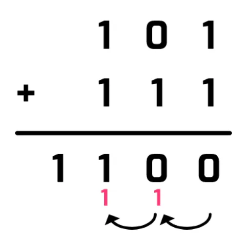
So to add two bits reliably in any column, three inputs are needed: the two bits, and the carry-in from the previous column. The circuit gives two outputs: the sum of the bits, and a carry-out to the next column. This circuit is a full adder, and it has this truth table:
| A | B | Cin | Cout | S |
|---|---|---|---|---|
| 0 | 0 | 0 | 0 | 0 |
| 0 | 0 | 1 | 0 | 1 |
| 0 | 1 | 0 | 0 | 1 |
| 0 | 1 | 1 | 1 | 0 |
| 1 | 0 | 0 | 0 | 1 |
| 1 | 0 | 1 | 1 | 0 |
| 1 | 1 | 0 | 1 | 0 |
| 1 | 1 | 1 | 1 | 1 |
You can build a full adder from two half adders. The first half adder works out A + B. The second half adder adds the sum from the first half adder to the carry-in from the previous column, which gives the final sum S. If either half adder has made a carry-out, the final carry-out must be 1, so the carry-outs of the two half adders go into an OR gate to give the final carry-out.
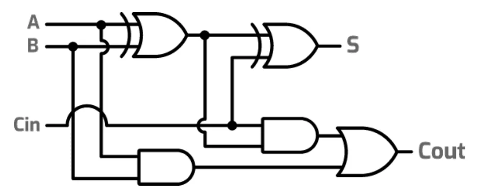
Binary full adders can be combined to build circuits that add very long binary numbers.
Practise this: past-paper questions
- June 2021 · Paper 31 · Q7(a)Complete the truth table for the given logic circuit. Show your working. Inputs | Working space | Outputs A | B | C | P | Q | R | Y | Z 0 | 0 | 0…
- June 2021 · Paper 31 · Q7(b)State the name of the logic circuit
- June 2021 · Paper 31 · Q7(c)Write the Boolean expressions for the two outputs Y and Z in the truth table as sum-of-products and state the purpose of each output
Used later in
15.2 · 3 of 21Book page Contents
Gates with three inputs
A gate can have more than two inputs. A three-input AND gate outputs 1 only when all three inputs are 1. A three-input OR gate outputs 1 when at least one input is 1. With three inputs there are 23 = 8 combinations, so the truth table has 8 rows.
When you complete a truth table for a longer expression or a logic circuit, work out each part in its own column first, then combine the columns.
Worked example
Complete the truth table for P = (A AND B AND C) OR NOT (B OR C).
- Step 1List the 8 combinations of A, B and C, counting up in binary from 000 to 111.
- Step 2Work out A AND B AND C: it is 1 only in the last row, where A, B and C are all 1.
- Step 3Work out B OR C, then NOT (B OR C): NOT (B OR C) is 1 only when B and C are both 0.
- Step 4P is 1 when either of those two columns is 1: in the rows 000, 100 and 111.
| A | B | C | A AND B AND C | B OR C | NOT (B OR C) | P |
|---|---|---|---|---|---|---|
| 0 | 0 | 0 | 0 | 0 | 1 | 1 |
| 0 | 0 | 1 | 0 | 1 | 0 | 0 |
| 0 | 1 | 0 | 0 | 1 | 0 | 0 |
| 0 | 1 | 1 | 0 | 1 | 0 | 0 |
| 1 | 0 | 0 | 0 | 0 | 1 | 1 |
| 1 | 0 | 1 | 0 | 1 | 0 | 0 |
| 1 | 1 | 0 | 0 | 1 | 0 | 0 |
| 1 | 1 | 1 | 1 | 1 | 0 | 1 |
Practise this: past-paper questions
- June 2021 · Paper 31 · Q7(a)Complete the truth table for the given logic circuit. Show your working. Inputs | Working space | Outputs A | B | C | P | Q | R | Y | Z 0 | 0 | 0…
- November 2023 · Paper 31 · Q6(a)Complete the truth table for the given logic circuit. | A | B | C | D | Z | | 0 | 0 | 0 | 0 | | | 0 | 0 | 0 | 1 | | | 0 | 0 | 1 | 0 | | | 0 | 0 |…
- November 2023 · Paper 32 · Q7(a)This logic circuit represents the Boolean expression: X = A + B + C [logic circuit diagram: inputs A, B, C; output X] Complete this truth table…
- June 2024 · Paper 31 · Q6(a)Complete the truth table for the given logic circuit. Show your working. | | | | Working space | | | A | B | C | P | Q | R | S | Z | | 0 | 0 | 0 |…
Show 5 more
- June 2024 · Paper 32 · Q6(a)Complete the truth table for the given logic circuit. Show your working. | | | | Working space | | | A | B | C | P | Q | R | S | T | Z | | 0 | 0 |…
- June 2025 · Paper 32 · Q7(a)Complete the truth table for the given logic circuit. Show your working. (P, Q, R and S are working space columns.) | A | B | C | D | P | Q | R |…
- November 2025 · Paper 31 · Q6(a)The diagram shows a logic circuit. Complete the truth table for the given logic circuit. Show your working. | | | | Working space | | | A | B | C…
- November 2025 · Paper 32 · Q6(a)The diagram shows a logic circuit. Complete the truth table for the given logic circuit. Show your working. | | | | Working space | | | A | B | C…
- June 2026 · Paper 31 · Q6(a)The diagram shows a logic circuit. [logic circuit diagram: inputs A, B and C; intermediate signals P, Q, R and S; output Z] Complete the truth…
15.2 · 4 of 21Book page Contents
The four-bit binary adder
Builds on
You do not need to know this circuit for the exam, but it shows how full adders can be chained together to add numbers with more than one bit.
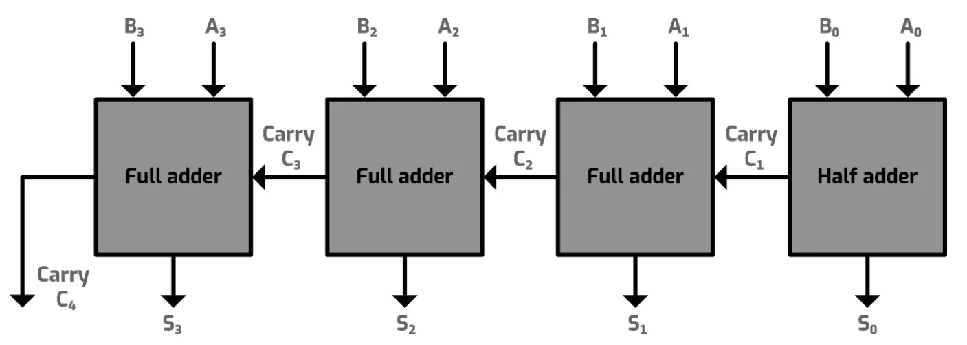
You can think of a full adder as one functional block with three inputs (A, B and Cin) and two outputs (Sum and Cout).
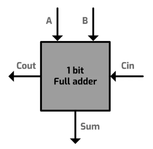
You can then chain together as many full adders as you need. The carry-out from one column feeds into the carry-in of the next column.
The diagram below shows a four-bit binary adder. The four-bit binary number A (split into the bits A0 to A3) is added to the four-bit binary number B, to give the four-bit binary number S and the final carry C4. The right-hand column is a half adder, because nothing is carried into the first column. The value of C4 can be used to control a status register, to show an overflow (a number that is too big to be represented using the current representation).
15.2 · 5 of 21Book page Contents
Sequential circuits and flip-flops
Builds on
All the circuits so far are combinational circuits (sometimes called combination circuits): their outputs depend only on their current inputs.
Flip-flops are different. They are sequential circuits: their outputs depend not only on the current inputs but also on the sequence of past inputs. A flip-flop lets a previous output value be stored, so it acts as a simple memory device. This memory is volatile: it does not keep its state when the power is switched off.
Sequential circuits can be asynchronous or synchronous:
- In an asynchronous circuit, the inputs are processed as soon as they arrive.
- In a synchronous circuit, the operations are controlled by a clock.
The clock in a computer system is an oscillator that produces a continuous stream of alternating signals, read as 1s and 0s. This clock signal is carried to every component of the computer system, to keep their operations in step. The time taken for one complete signal, one high (1) and one low (0), is called a clock cycle.
Purpose of a flip-flop
- A flip-flop stores a previous output value (one bit), so it acts as a simple memory device.
Practise this: past-paper questions
15.2 · 6 of 21Book pages Contents
The SR flip-flop (NOR gates)
Builds on
An SR flip-flop is a simple one-bit memory device. It is an asynchronous sequential circuit built from two cross-coupled NOR gates: the output of each gate feeds back in as an input to the other gate. A similar circuit can be built with NAND gates.
The circuit has two inputs, S and R. S is used to SET the device and R is used to RESET it. It also has two outputs, Q and NOT Q.
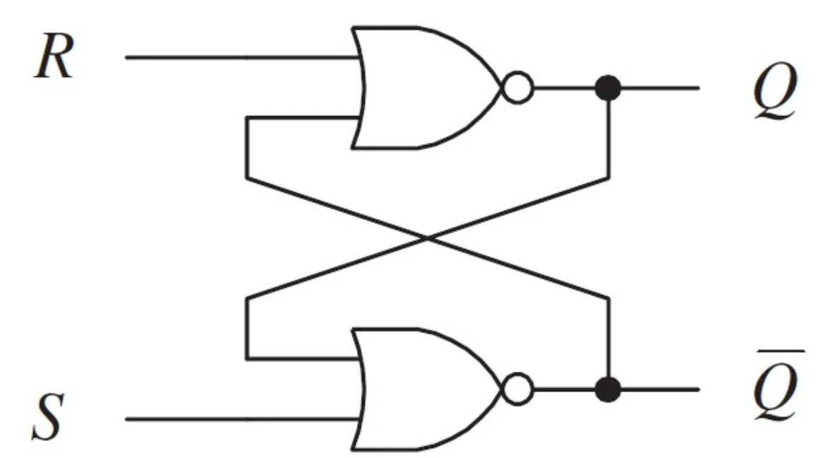
- When S = 1 and R = 0, the output Q is 1: S sets the flip-flop.
- When S = 0 and R = 1, the output Q is 0: R resets the flip-flop.
- After it has been set or reset, when S = 0 and R = 0, the previous value of Q is kept by the feedback loop until the circuit is set or reset again. This is how the circuit acts as a one-bit memory device.
| S | R | Q | NOT Q |
|---|---|---|---|
| 0 | 0 | As previous | As previous |
| 0 | 1 | 0 | 1 |
| 1 | 0 | 1 | 0 |
| 1 | 1 | Illegal | Illegal |
The circuit must not allow both inputs to be 1. If you follow the logic, S = 1 and R = 1 would make both Q and NOT Q equal 0, which is contradictory. This is called an illegal state.
The SR flip-flop can be unstable if the inputs do not arrive at the same time. This can be improved by using a clock signal to synchronise the gates’ operation.
Practise this: past-paper questions
15.2 · 7 of 21Book pages Contents
The SR flip-flop with NAND gates
Builds on
An SR flip-flop can also be made by cross-coupling two NAND gates, but then the hold and forbidden (illegal) states are the other way round: the hold state is when both inputs are 1, and the illegal state is when both inputs are 0. It is an active-low SR flip-flop: an input does its job when it is 0, not 1. So its inputs are labelled NOT S and NOT R (S and R with a bar over them), and this version is called the NOT R NOT S flip-flop.
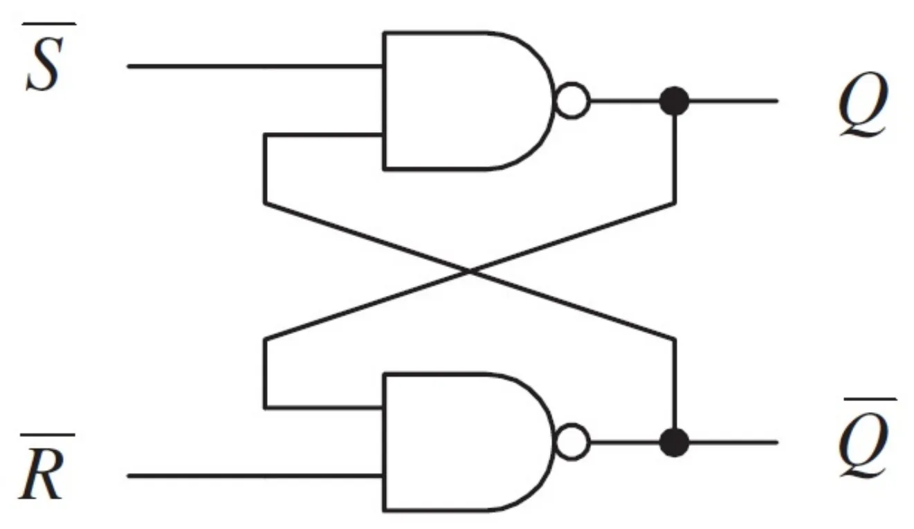
The important point about a NAND gate is that its dominating input is 0: if any of its inputs is 0, the output is 1, whatever the other input is. The output is 0 only if all the inputs are 1. With this in mind, the NAND-based flip-flop works like this:
| NOT R | NOT S | Q | NOT Q |
|---|---|---|---|
| 1 | 1 | As previous | As previous |
| 1 | 0 | 1 | 0 |
| 0 | 1 | 0 | 1 |
| 0 | 0 | Illegal | Illegal |
In practice, a clock (enable) input is usually added, so the flip-flop can only change state when the clock signal allows it. This is called a clocked SR flip-flop, and it is what “SR flip-flop” normally means.
Practise this: past-paper questions
15.2 · 8 of 21Book pages Contents
The JK flip-flop
Builds on
The JK flip-flop is the most widely used flip-flop. It is more stable than an SR flip-flop and more flexible than a D-type flip-flop. It has two inputs, J and K, as well as the clock signal (Clk), so it has four functions: SET, RESET, HOLD and TOGGLE.
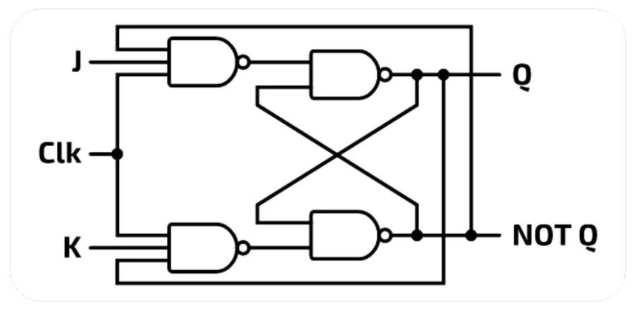
When the clock signal is low (0), the outputs do not change. When the clock signal is high (1):
- J = 0 and K = 0: there is no change to Q (HOLD).
- J = 0 and K = 1: the flip-flop is RESET, so Q = 0.
- J = 1 and K = 0: the flip-flop is SET, so Q = 1.
- J = 1 and K = 1: the value of Q will toggle (change to the opposite value).
Because J = 1 and K = 1 toggles Q instead of giving contradictory outputs, the JK flip-flop prevents the illegal states that cannot be allowed in an SR flip-flop.
| Clk | J | K | Q | NOT Q |
|---|---|---|---|---|
| 1 | 0 | 0 | As previous | As previous |
| 1 | 0 | 1 | 0 | 1 |
| 1 | 1 | 0 | 1 | 0 |
| 1 | 1 | 1 | Toggle | Toggle |
Several JK flip-flops can be used to make shift registers in a computer system, and a simple binary counter can be made by connecting several JK flip-flops together.
15.2 · 9 of 21Book page Contents
Boolean algebra
Boolean algebra is a formal way of writing logical statements. It was introduced by George Boole, an English mathematician, in his book “The Mathematical Analysis of Logic” (1847).
In Boolean algebra the basic logic gate operations (AND, OR, XOR and NOT) are replaced with symbols. In these notes AND is written as a dot (A . B), OR as a plus (A + B), and NOT is written in words (NOT A, or NOT(A . B) for a whole bracket). In the book and in exam papers, NOT is drawn as a bar over the letter or over the bracket.
Knowing the Boolean identities (next section) lets us simplify logic statements. For example, a complicated circuit made of 20 logic gates may simplify to only 5 or 6 gates, which makes the circuit cheaper to manufacture.
Used later in
15.2 · 10 of 21Book pages Contents
Boolean identities (the laws)
Boolean identities are equivalences that are true for every possible set of input values. Each law comes as a pair: one for AND and one for OR.
| Law | Equivalences | Further explanation |
|---|---|---|
| Identity laws | 1 . A = A; 0 + A = A | True AND A is the same as just A. Likewise, False OR A is the same as just A. |
| Double complement law | NOT NOT A = A | NOT NOT A is the same as A: if you invert something twice, you get back the original value. |
| Dominance laws | 0 . A = 0; 1 + A = 1 | False AND A is always False. True OR A is always True. |
| Idempotence laws | A . A = A; A + A = A | A AND A is the same as just A. A OR A is also the same as just A. |
| Inverse laws | A . NOT A = 0; A + NOT A = 1 | A AND NOT A is always False. A OR NOT A is always True. |
| Commutative laws | A . B = B . A; A + B = B + A | A AND B is exactly the same as B AND A, and A OR B is exactly the same as B OR A. The order of two inputs joined by a logic gate does not matter. |
| Absorption laws | A . (A + B) = A; A + (A . B) = A | A AND (A OR B) is the same as just A. Likewise, A OR (A AND B) is the same as just A. |
| Associative laws | (A . B) . C = A . (B . C); (A + B) + C = A + (B + C) | When three inputs are joined by two AND gates, the order they are joined in does not matter. The same is true for three inputs joined by OR gates. |
| Distributive laws | A . (B + C) = (A . B) + (A . C); A + (B . C) = (A + B) . (A + C) | This is like multiplying out brackets: 5 × (6 + 2) is the same as (5 × 6) + (5 × 2). Take care to use the right Boolean symbols, as they are easy to get wrong. |
Most of the identities make common sense when they are turned into sentences. The idempotence laws say that "I will go to bed if I am tired or I am tired" reduces to just "I will go to bed if I am tired". The inverse laws say that "it is the weekend and it is not the weekend" is always False.
Practise this: past-paper questions
- November 2021 · Paper 32 · Q7(b)(iv)Write the simplified Boolean expression for your answer to part b(iii)
- November 2022 · Paper 31 · Q7(c)Write the Boolean expression from your answer to part (b) as a simplified sum-of-products. Use Boolean algebra to give your answer in its simplest…
- November 2022 · Paper 32 · Q8(c)Simplify the following expression using Boolean algebra, including De Morgan’s laws. Show your working. (A.B).(A.C).(B.D)
- June 2023 · Paper 31 · Q7(d)Use Boolean algebra to give your answer to part (c) in its simplest form. Z
Show 9 more
- June 2023 · Paper 32 · Q9(e)Use Boolean algebra to give your answer to part (d) in its simplest form. Z
- November 2023 · Paper 31 · Q6(b)Simplify the given Boolean expression using Boolean algebra. Show your working. Y = A.B.C.D + A.B.C.D + A.B.C.D + A.B.C.D
- November 2023 · Paper 32 · Q7(c)Simplify the following expression using Boolean algebra. Show all the stages in your simplification. T = X.Y.Z + X.Y.Z + X
- November 2024 · Paper 31 · Q7(d)(ii)Use Boolean algebra to write your answer to part (d)(i) in its simplest form. T
- June 2025 · Paper 32 · Q7(c)Use Boolean algebra including De Morgan’s laws to simplify the following expression. Show all working. (A̅+̅B̅).(A̅.̅B̅ + B̅.̅C̅)
- November 2025 · Paper 33 · Q6(b)Simplify the following expression using De Morgan’s laws and Boolean algebra. Show all the stages in your simplification. X = NOT(A̅ + B + C̅) +…
- June 2026 · Paper 32 · Q7(b)Simplify the following expression using De Morgan’s laws and Boolean algebra. Show all the stages in your simplification. X = A̿.̅B̅.̅C̅.̅D̿ + A̿.̿D̿
- June 2026 · Paper 33 · Q6(a)(iii)Write the Boolean expression from your answer to 6(a)(ii) in its simplest form by using Boolean algebra to simplify it
- June 2026 · Paper 33 · Q6(b)Simplify the following expression using De Morgan’s laws and Boolean algebra. Show all the stages in your simplification. X = A̅+̅B̅+̅C̅ + B̅+̅C̅
15.2 · 11 of 21Book page Contents
De Morgan’s laws
One pair of laws that is less linked to common sense or basic mathematics is De Morgan’s laws, named after the nineteenth-century British mathematician Augustus De Morgan.
| Equivalence | Further explanation |
|---|---|
| NOT(A . B) = (NOT A) + (NOT B) | NOT(A AND B) is the same as (NOT A) OR (NOT B). |
| NOT(A + B) = (NOT A) . (NOT B) | NOT(A OR B) is the same as (NOT A) AND (NOT B). |
How to use De Morgan’s laws
- The NOT over the whole bracket is split into a NOT on each input.
- When you expand the bracket, the gate changes: AND becomes OR, and OR becomes AND.
Practise this: past-paper questions
- November 2022 · Paper 32 · Q8(c)Simplify the following expression using Boolean algebra, including De Morgan’s laws. Show your working. (A.B).(A.C).(B.D)
- November 2023 · Paper 32 · Q7(b)Apply De Morgan’s laws to the expression: X = A + B + C X
- June 2025 · Paper 32 · Q7(c)Use Boolean algebra including De Morgan’s laws to simplify the following expression. Show all working. (A̅+̅B̅).(A̅.̅B̅ + B̅.̅C̅)
- November 2025 · Paper 33 · Q6(b)Simplify the following expression using De Morgan’s laws and Boolean algebra. Show all the stages in your simplification. X = NOT(A̅ + B + C̅) +…
Show 2 more
- June 2026 · Paper 32 · Q7(b)Simplify the following expression using De Morgan’s laws and Boolean algebra. Show all the stages in your simplification. X = A̿.̅B̅.̅C̅.̅D̿ + A̿.̿D̿
- June 2026 · Paper 33 · Q6(b)Simplify the following expression using De Morgan’s laws and Boolean algebra. Show all the stages in your simplification. X = A̅+̅B̅+̅C̅ + B̅+̅C̅
15.2 · 12 of 21Book pages Contents
Simplifying expressions with the laws
Builds on
To simplify an expression, apply one law at a time and name the law you used at each step.
Worked example
Simplify the expression A . (A + B) + NOT A.
- Step 1Use the absorption laws to replace A . (A + B) with A.
- Step 2The expression is now A + NOT A.
- Step 3The inverse law states that A + NOT A = 1. So the expression will always output 1.
Worked example
Simplify the expression NOT(A . NOT B).
- Step 1Use De Morgan’s law to replace NOT(A . NOT B) with (NOT A) + (NOT NOT B).
- Step 2Use the double complement law to replace NOT NOT B with B.
- Step 3The simplified expression is therefore NOT A + B.
Try these guided questions before looking at the last step, which gives the answer.
Guided question 1
Simplify the expression 0 + (1 . A).
- Step 1Use the identity laws to simplify the contents of the brackets.
- Step 2Decide whether the resulting expression can be simplified any further.
- Step 3Answer: 0 + (1 . A) = 0 + A = A (identity laws).
Guided question 2
A logic circuit manufacturer has a limited stock of OR gates. Rewrite the expression NOT((A + A) + B) so that no OR gates are used.
- Step 1Use an appropriate law to simplify (A + A).
- Step 2Use De Morgan’s laws to rewrite the resulting expression without using +.
- Step 3Answer: A + A = A (idempotence law), so NOT((A + A) + B) = NOT(A + B) = NOT A . NOT B (De Morgan’s law). This uses only AND and NOT gates.
Guided question 3
Simplify the expression B + NOT(A . B).
- Step 1Apply De Morgan’s laws to the expression where appropriate.
- Step 2Another law can simplify this even further. You may need the associative laws to rearrange the order of the expression so that this becomes obvious.
- Step 3Write down the new, simplified version of the expression.
Answer to guided question 3, one law at a time:
| Expression | Law used |
|---|---|
| B + NOT(A . B) = B + NOT A + NOT B | De Morgan’s law |
| = NOT A + (B + NOT B) | commutative and associative laws |
| = NOT A + 1 | inverse law |
| = 1 | dominance law |
Practise this: past-paper questions
- November 2021 · Paper 32 · Q7(b)(iv)Write the simplified Boolean expression for your answer to part b(iii)
- November 2022 · Paper 31 · Q7(c)Write the Boolean expression from your answer to part (b) as a simplified sum-of-products. Use Boolean algebra to give your answer in its simplest…
- November 2022 · Paper 32 · Q8(c)Simplify the following expression using Boolean algebra, including De Morgan’s laws. Show your working. (A.B).(A.C).(B.D)
- June 2023 · Paper 31 · Q7(d)Use Boolean algebra to give your answer to part (c) in its simplest form. Z
Show 9 more
- June 2023 · Paper 32 · Q9(e)Use Boolean algebra to give your answer to part (d) in its simplest form. Z
- November 2023 · Paper 31 · Q6(b)Simplify the given Boolean expression using Boolean algebra. Show your working. Y = A.B.C.D + A.B.C.D + A.B.C.D + A.B.C.D
- November 2023 · Paper 32 · Q7(c)Simplify the following expression using Boolean algebra. Show all the stages in your simplification. T = X.Y.Z + X.Y.Z + X
- November 2024 · Paper 31 · Q7(d)(ii)Use Boolean algebra to write your answer to part (d)(i) in its simplest form. T
- June 2025 · Paper 32 · Q7(c)Use Boolean algebra including De Morgan’s laws to simplify the following expression. Show all working. (A̅+̅B̅).(A̅.̅B̅ + B̅.̅C̅)
- November 2025 · Paper 33 · Q6(b)Simplify the following expression using De Morgan’s laws and Boolean algebra. Show all the stages in your simplification. X = NOT(A̅ + B + C̅) +…
- June 2026 · Paper 32 · Q7(b)Simplify the following expression using De Morgan’s laws and Boolean algebra. Show all the stages in your simplification. X = A̿.̅B̅.̅C̅.̅D̿ + A̿.̿D̿
- June 2026 · Paper 33 · Q6(a)(iii)Write the Boolean expression from your answer to 6(a)(ii) in its simplest form by using Boolean algebra to simplify it
- June 2026 · Paper 33 · Q6(b)Simplify the following expression using De Morgan’s laws and Boolean algebra. Show all the stages in your simplification. X = A̅+̅B̅+̅C̅ + B̅+̅C̅
15.2 · 13 of 21Book pages Contents
Karnaugh maps and truth tables
A Karnaugh map (also called a K-map) is a version of a truth table for a Boolean expression, laid out in a way that makes the expression easier to simplify.
Take the expression A + (A . B). Its truth table is:
| A | B | A + (A . B) |
|---|---|---|
| 0 | 0 | 0 |
| 0 | 1 | 0 |
| 1 | 0 | 1 |
| 1 | 1 | 1 |
The truth table has four rows because there are two inputs, so 22 combinations of 1s and 0s. Each row shows the output for one combination of input values.
A Karnaugh map is a variation on a truth table, arranged so that:
- the number of output cells matches the number of rows in the truth table
- the possible input values for the variables in the expression form the row and column headings
- the output for each combination of input values is written where its row and column meet.
Here is the Karnaugh map for A + (A . B). The values of A are the column headings and the values of B are the row headings. Where a row and a column meet is the output for those inputs.
| B \ A | 0 | 1 |
|---|---|---|
| 0 | 0 | 1 |
| 1 | 0 | 1 |
In a Karnaugh map you circle groups of 1s whose size is a power of 2 (1, 2, 4 or 8 cells, but not 3, 5 or 6). Here there is only one group: the two 1s in the column where A = 1. As it is the only group, the expression simplifies to A.
Practise this: past-paper questions
Used later in
15.2 · 14 of 21Book pages Contents
Drawing a Karnaugh map
Builds on
These are the steps for drawing the Karnaugh map of A + (A . B):
- Create a grid. The number of rows and columns depends on the number of variables in the expression.
- Break up the expression at the ORs. This gives two parts: A, and A . B.
- Take the first part: write a 1 wherever A is True. This means 1s in both cells of the right-hand column.
- Take the second part: write a 1 wherever A . B is True. This is the bottom right-hand cell, but there is already a 1 there, so nothing more is needed.
- Write 0s in the empty cells (or leave them blank).
- Circle every group of 1s whose size is a power of 2 (groups of 1, 2, 4 or 8 cells).
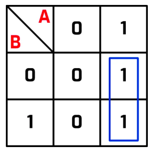
There is a single circled group of 1s, in the column where A = 1. As it is the only group, the expression simplifies to A.
Note An expression made of AND terms joined by OR, such as A . B + NOT A . B, is called a sum of products. Breaking it up at the ORs, as in step 2, gives one term to place on the map at a time. To write one from a truth table, take each row where the output is 1, write its inputs joined by AND (with NOT on each input that is 0 in that row), then join these terms with +. For example, outputs of 1 in the rows A = 0, B = 1 and A = 1, B = 1 give NOT A . B + A . B.
Rules for grouping 1s
- Groups must be horizontal or vertical: no diagonals are allowed.
- The number of cells in each group must be a power of 2.
- Groups should be as large as possible.
- Every 1 in the map must be in at least one group.
- Make the smallest number of groups possible.
Practise this: past-paper questions
- June 2021 · Paper 31 · Q7(c)Write the Boolean expressions for the two outputs Y and Z in the truth table as sum-of-products and state the purpose of each output
- November 2021 · Paper 32 · Q7(a)Write the Boolean expression that corresponds to the given truth table as a sum-of-products
- November 2021 · Paper 32 · Q7(b)(i)Complete the Karnaugh map (K-map) for the given truth table. AB | 00 | 01 | 11 | 10 CD 00 | | | | 01 | | | | 11 | | | | 10 | | | |
- November 2021 · Paper 32 · Q7(b)(ii)Draw loop(s) around appropriate group(s) of 1s in the K-map to produce an optimal sum-of-products
Show 35 more
- November 2022 · Paper 31 · Q7(a)Complete the Karnaugh map (K-map) for the Boolean expression. Z = Ā. B. C̄. D̄ + Ā. B. C̄. D + A. B. C̄. D̄ + A. B. C̄. D + A. B̄. C̄. D̄ + A.…
- November 2022 · Paper 31 · Q7(b)Draw loop(s) around appropriate group(s) in the K-map to produce an optimal sum-of-products
- June 2023 · Paper 31 · Q7(a)Complete the Karnaugh map (K-map) for the following Boolean expression. Z = A.B.C.D + A.B.C.D + A.B.C.D + A.B.C.D + A.B.C.D + A.B.C.D [NOTE:…
- June 2023 · Paper 31 · Q7(b)Draw loop(s) around appropriate group(s) in the K-map to produce an optimal sum-of-products
- June 2023 · Paper 32 · Q9(a)Write the Boolean logic expression that corresponds to the given truth table as the sum-of-products. Z
- June 2023 · Paper 32 · Q9(b)Complete the Karnaugh map (K-map) for the given truth table. AB CD | 00 | 01 | 11 | 10 00 | | | | 01 | | | | 11 | | | | 10 | | | |
- June 2023 · Paper 32 · Q9(c)Draw loop(s) around appropriate group(s) in the K-map to produce an optimal sum-of-products
- June 2024 · Paper 31 · Q6(b)Write the Boolean expression that corresponds to the logic circuit as a sum-of-products. Z
- June 2024 · Paper 31 · Q6(c)(i)Complete the Karnaugh map (K-map) for the Boolean expression: A.B.C + A.B.C + A.B.C + A.B.C + A.B.C + A.B.C | BC | 00 | 01 | 11 | 10 | | A 0 | | |…
- June 2024 · Paper 31 · Q6(c)(ii)Draw loop(s) around appropriate group(s) in the K-map to produce an optimal sum-of-products
- June 2024 · Paper 32 · Q6(b)Write the Boolean expression that corresponds to the logic circuit as a sum-of-products. Z
- June 2024 · Paper 32 · Q6(c)(i)Complete the Karnaugh map (K-map) for this Boolean expression: A.B.C + A.B.C + A.B.C + A.B.C + A.B.C + A.B.C | BC | 00 | 01 | 11 | 10 | | A 0 | |…
- June 2024 · Paper 32 · Q6(c)(ii)Draw loop(s) around appropriate group(s) in the K-map to produce an optimal sum-of-products
- November 2024 · Paper 31 · Q7(a)Write the Boolean logic expression that corresponds to the given truth table as the sum-of-products. T
- November 2024 · Paper 31 · Q7(b)Complete the Karnaugh map (K-map) for the given truth table. AB CD | 00 | 01 | 11 | 10 | 00 | | | | | 01 | | | | | 11 | | | | | 10 | | | | |
- November 2024 · Paper 31 · Q7(c)Draw loop(s) around appropriate group(s) in the K-map to produce an optimal sum-of-products
- November 2024 · Paper 32 · Q6(a)Write the Boolean logic expression that corresponds to the given truth table as the sum-of-products. X
- November 2024 · Paper 32 · Q6(b)Complete the Karnaugh map (K-map) for the given truth table. AB CD | 00 | 01 | 11 | 10 | 00 | | | | | 01 | | | | | 11 | | | | | 10 | | | | |
- November 2024 · Paper 32 · Q6(c)Draw loop(s) around appropriate group(s) in the K-map to produce an optimal sum-of-products
- June 2025 · Paper 31 · Q5(a)Write the Boolean logic expression that corresponds to the given truth table as the sum-of-products
- June 2025 · Paper 31 · Q5(b)(i)Complete the Karnaugh map (K-map) for the given truth table. CD \ AB | 00 | 01 | 11 | 10 00 | | | | 01 | | | | 11 | | | | 10 | | | |
- June 2025 · Paper 31 · Q5(b)(ii)Draw loop(s) around appropriate group(s) in the K-map to produce an optimal sum-of-products
- June 2025 · Paper 32 · Q7(b)Write the Boolean logic expression that corresponds to the given logic circuit as the sum-of-products
- June 2025 · Paper 33 · Q3(a)Write the Boolean logic expression that corresponds to the given truth table as the sum-of-products. Z
- June 2025 · Paper 33 · Q3(b)(i)Complete the Karnaugh map (K-map) for the given truth table. AB CD | 00 | 01 | 11 | 10 00 | | | | 01 | | | | 11 | | | | 10 | | | |
- June 2025 · Paper 33 · Q3(b)(ii)Draw loop(s) around appropriate group(s) in the K-map to produce an optimal sum-of-products
- November 2025 · Paper 31 · Q6(b)(i)Complete the Karnaugh map (K-map) for the Boolean expression: A.B.C + A.B.C + A.B.C + A.B.C | | BC | | | | | A | 00 | 01 | 11 | 10 | | 0 | | | | |…
- November 2025 · Paper 31 · Q6(b)(ii)Draw loop(s) around appropriate group(s) in the K-map to produce an optimal sum-of-products
- November 2025 · Paper 32 · Q6(b)(i)Complete the Karnaugh map (K-map) for the Boolean expression: A.B.C + A.B.C + A.B.C + A.B.C | | BC | | | | | A | 00 | 01 | 11 | 10 | | 0 | | | | |…
- November 2025 · Paper 32 · Q6(b)(ii)Draw loop(s) around appropriate group(s) in the K-map to produce an optimal sum-of-products
- November 2025 · Paper 33 · Q6(a)(i)Draw loop(s) around appropriate group(s) in the K-map to produce an optimal sum-of-products
- June 2026 · Paper 31 · Q6(c)(i)Draw loop(s) around appropriate group(s) in the K-map to produce an optimal sum-of-products
- June 2026 · Paper 32 · Q7(a)(i)Complete the Karnaugh map (K-map) for the given truth table. | | AB | | | | | CD | 00 | 01 | 11 | 10 | | 00 | | | | | | 01 | | | | | | 11 | | | |…
- June 2026 · Paper 32 · Q7(a)(ii)Draw loop(s) around appropriate group(s) in the K-map to produce an optimal sum-of-products
- June 2026 · Paper 33 · Q6(a)(i)Draw loop(s) around appropriate group(s) in the K-map to produce an optimal sum-of-products
15.2 · 15 of 21Book pages Contents
Worked example: a two-input map
Worked example
Use a Karnaugh map to simplify A . B + NOT A . B.
- Step 1Create a grid with two rows and two columns: A across the top, B down the side.
- Step 2Break up the expression at the OR. This gives two separate expressions: A . B and NOT A . B.
- Step 3Put a 1 where A . B is True: the cell where A = 1 and B = 1 (bottom right).
- Step 4Put a 1 where NOT A . B is True: the cell where A = 0 and B = 1 (bottom left). There is already a 1 in the bottom right-hand cell, so leave it.
- Step 5If you like, write 0s in the blank cells.
- Step 6Circle any groups whose number of 1s is a power of 2 (1, 2, 4 or 8 cells). Here the two 1s in the bottom row make one group.
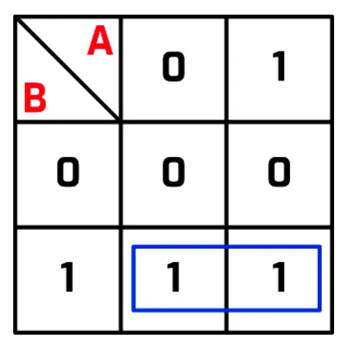
The circled group shows that the output is 1 whenever B is 1, so the expression simplifies to B.
15.2 · 16 of 21Book page Contents
Reading the expression from a Karnaugh map
Builds on
Here is a map with more than one group of 1s. To find the expression it represents, look at each circled group in turn and see which input or inputs stay the same across the whole group.
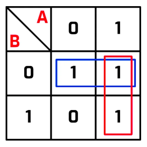
- The blue, horizontal group shows that the output is always 1 when B is 0, so this group represents NOT B.
- The red, vertical group shows that the output is always 1 when A is 1, so this group represents A.
Join the expressions for the groups with +. This map represents A + NOT B.
Useful fact
- If every output cell in a Karnaugh map holds 1, the expression simplifies to 1.
- If every cell holds 0, it simplifies to 0.
Practise this: past-paper questions
- November 2021 · Paper 32 · Q7(b)(iii)Write the Boolean expression from your answer to part b(ii) as a simplified sum-of-products
- November 2022 · Paper 31 · Q7(c)Write the Boolean expression from your answer to part (b) as a simplified sum-of-products. Use Boolean algebra to give your answer in its simplest…
- June 2023 · Paper 31 · Q7(c)Write the Boolean logic expression from your answer to part (b) as a simplified sum-of-products. Z
- June 2023 · Paper 32 · Q9(d)Write the Boolean logic expression from your answer to part (c) as a simplified sum-of-products. Z
Show 12 more
- June 2024 · Paper 31 · Q6(c)(iii)Write the Boolean expression from your answer to part (c)(ii) as a simplified sum-of-products
- June 2024 · Paper 32 · Q6(c)(iii)Write the Boolean expression from your answer to part c(ii) as a simplified sum-of-products
- November 2024 · Paper 31 · Q7(d)(i)Write the Boolean logic expression from your answer to part (c) as the simplified sum-of-products. T
- November 2024 · Paper 32 · Q6(d)Write the Boolean logic expression from your answer to part (c) as the simplified sum-of-products. X
- June 2025 · Paper 31 · Q5(b)(iii)Write the Boolean logic expression from your answer to part (b)(ii) as the simplified sum-of-products
- June 2025 · Paper 33 · Q3(b)(iii)Write the Boolean logic expression from your answer to part (b)(ii) as the simplified sum-of-products. Z
- November 2025 · Paper 31 · Q6(b)(iii)Write the Boolean expression from your answer to part b(ii) as a simplified sum-of-products. Do not carry out any further simplification
- November 2025 · Paper 32 · Q6(b)(iii)Write the Boolean expression from your answer to part b(ii) as a simplified sum-of-products. Do not carry out any further simplification
- November 2025 · Paper 33 · Q6(a)(ii)Write the Boolean expression from your answer to part a(i) as a simplified sum-of-products. Do not carry out any further simplification
- June 2026 · Paper 31 · Q6(c)(ii)Write the Boolean expression from your answer to 6(c)(i) as a simplified sum-of-products. Do not carry out any further simplification
- June 2026 · Paper 32 · Q7(a)(iii)Write the Boolean expression from your answer to 7(a)(ii) as a simplified sum-of-products
- June 2026 · Paper 33 · Q6(a)(ii)Write the Boolean expression from your answer to 6(a)(i) as a simplified sum-of-products. Do not carry out any further simplification
15.2 · 17 of 21Book pages Contents
Three-input Karnaugh maps
Builds on
In a Karnaugh map with three inputs, one side of the map represents two of the inputs. Consider the expression (A . B) + (A . B . C). In its map:
- there are four rows for the possible values of the inputs AB
- there are two columns for the possible values of the input C.
| AB \ C | 0 | 1 |
|---|---|---|
| 00 | ||
| 01 | ||
| 11 | ||
| 10 |
It does not matter how you split the inputs, so this map could also be drawn with two rows and four columns. But the order of the input values matters: on a side with two inputs (here AB), only one of the two values may change from one cell to the next. So 01 can never be next to 10, and the order is 00, 01, 11, 10, which is different from the usual order of rows in a truth table.
Now fill in the map:
- Split the expression at the +. This gives A . B and A . B . C.
- Put a 1 in the cells where A . B is True.
- Put a 1 in the cells where A . B . C is True. Here that cell (AB = 11, C = 1) already holds a 1.
- Circle groups whose number of 1s is a power of 2 (1, 2, 4 or 8 cells).
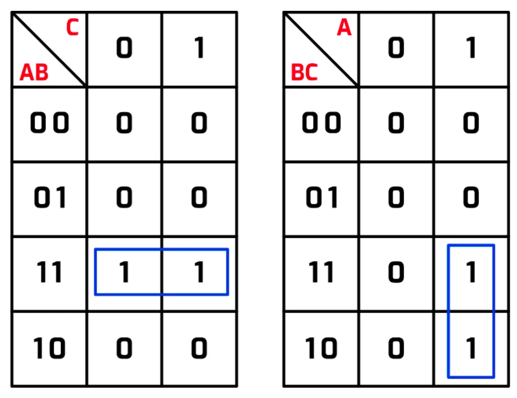
The map is shown in two forms. The map on the right groups the inputs differently, but gives the same result: the grouping of inputs does not matter. The circled group of 1s is where both A and B are 1, so the simplified expression is A . B.
Practise this: past-paper questions
- June 2024 · Paper 31 · Q6(c)(i)Complete the Karnaugh map (K-map) for the Boolean expression: A.B.C + A.B.C + A.B.C + A.B.C + A.B.C + A.B.C | BC | 00 | 01 | 11 | 10 | | A 0 | | |…
- June 2024 · Paper 32 · Q6(c)(i)Complete the Karnaugh map (K-map) for this Boolean expression: A.B.C + A.B.C + A.B.C + A.B.C + A.B.C + A.B.C | BC | 00 | 01 | 11 | 10 | | A 0 | |…
- November 2025 · Paper 31 · Q6(b)(i)Complete the Karnaugh map (K-map) for the Boolean expression: A.B.C + A.B.C + A.B.C + A.B.C | | BC | | | | | A | 00 | 01 | 11 | 10 | | 0 | | | | |…
- November 2025 · Paper 32 · Q6(b)(i)Complete the Karnaugh map (K-map) for the Boolean expression: A.B.C + A.B.C + A.B.C + A.B.C | | BC | | | | | A | 00 | 01 | 11 | 10 | | 0 | | | | |…
Used later in
15.2 · 18 of 21Book pages Contents
Four-input Karnaugh maps
Builds on
Karnaugh maps in A Level exam questions can have up to four inputs. Take the expression C + (C . A . B . D). In its empty map:
- there are four columns for the possible values of the inputs AB
- there are four rows for the possible values of the inputs CD
- on each side, only one value of each pair changes from one cell to the next (the order 00, 01, 11, 10).
| CD \ AB | 00 | 01 | 11 | 10 |
|---|---|---|---|---|
| 00 | ||||
| 01 | ||||
| 11 | ||||
| 10 |
Using the same method as before, place 1s on the map for each of the two parts of the expression: C, and C . A . B . D.
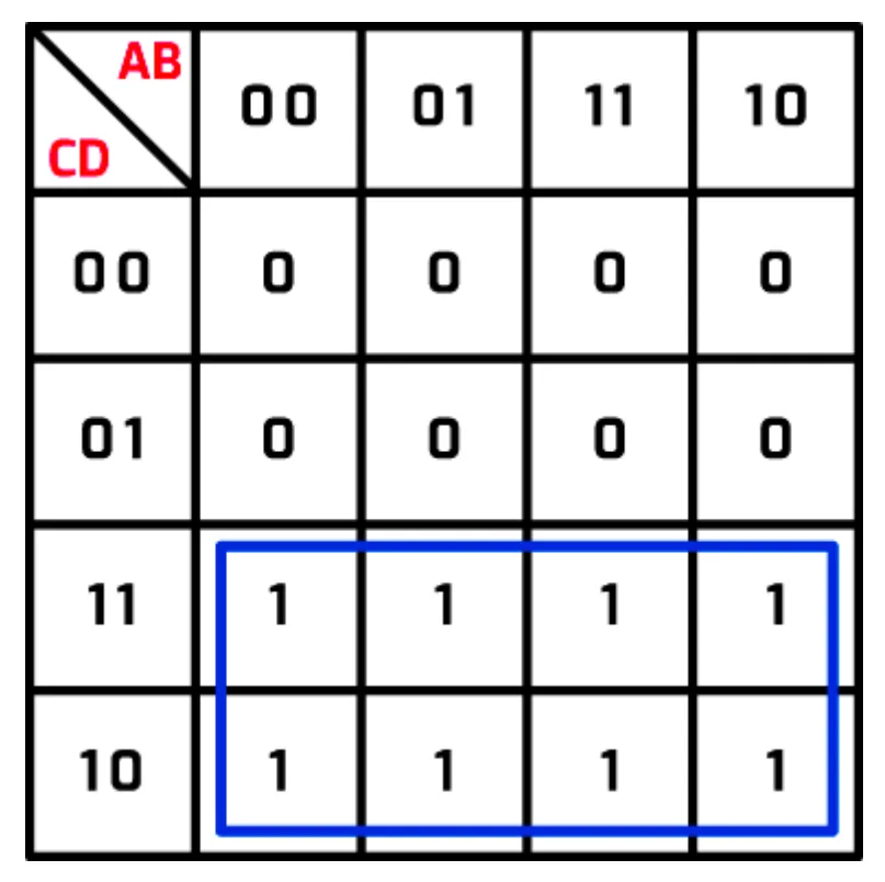
This time there is one big group of eight 1s to circle. It shows that the output is always 1 when C is 1, so the expression simplifies to C.
Practise this: past-paper questions
- November 2021 · Paper 32 · Q7(b)(i)Complete the Karnaugh map (K-map) for the given truth table. AB | 00 | 01 | 11 | 10 CD 00 | | | | 01 | | | | 11 | | | | 10 | | | |
- November 2022 · Paper 31 · Q7(a)Complete the Karnaugh map (K-map) for the Boolean expression. Z = Ā. B. C̄. D̄ + Ā. B. C̄. D + A. B. C̄. D̄ + A. B. C̄. D + A. B̄. C̄. D̄ + A.…
- June 2023 · Paper 31 · Q7(a)Complete the Karnaugh map (K-map) for the following Boolean expression. Z = A.B.C.D + A.B.C.D + A.B.C.D + A.B.C.D + A.B.C.D + A.B.C.D [NOTE:…
- June 2023 · Paper 32 · Q9(b)Complete the Karnaugh map (K-map) for the given truth table. AB CD | 00 | 01 | 11 | 10 00 | | | | 01 | | | | 11 | | | | 10 | | | |
Show 5 more
- November 2024 · Paper 31 · Q7(b)Complete the Karnaugh map (K-map) for the given truth table. AB CD | 00 | 01 | 11 | 10 | 00 | | | | | 01 | | | | | 11 | | | | | 10 | | | | |
- November 2024 · Paper 32 · Q6(b)Complete the Karnaugh map (K-map) for the given truth table. AB CD | 00 | 01 | 11 | 10 | 00 | | | | | 01 | | | | | 11 | | | | | 10 | | | | |
- June 2025 · Paper 31 · Q5(b)(i)Complete the Karnaugh map (K-map) for the given truth table. CD \ AB | 00 | 01 | 11 | 10 00 | | | | 01 | | | | 11 | | | | 10 | | | |
- June 2025 · Paper 33 · Q3(b)(i)Complete the Karnaugh map (K-map) for the given truth table. AB CD | 00 | 01 | 11 | 10 00 | | | | 01 | | | | 11 | | | | 10 | | | |
- June 2026 · Paper 32 · Q7(a)(i)Complete the Karnaugh map (K-map) for the given truth table. | | AB | | | | | CD | 00 | 01 | 11 | 10 | | 00 | | | | | | 01 | | | | | | 11 | | | |…
15.2 · 19 of 21Book page Contents
Overlapping groups
Here is a four-input Karnaugh map with two overlapping groups of 1s. A 1 may belong to more than one group.
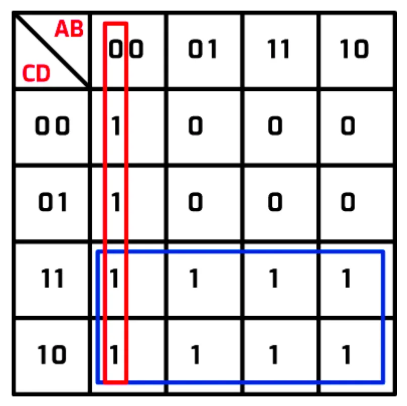
- The large blue group of eight 1s represents C, as in the section before.
- In the red, vertical group, A and B are both always 0. So this group represents NOT A . NOT B.
Join the two expressions with a + (OR) to get the expression this map represents: (NOT A . NOT B) + C.
Practise this: past-paper questions
- November 2021 · Paper 32 · Q7(b)(ii)Draw loop(s) around appropriate group(s) of 1s in the K-map to produce an optimal sum-of-products
- November 2022 · Paper 31 · Q7(b)Draw loop(s) around appropriate group(s) in the K-map to produce an optimal sum-of-products
- June 2023 · Paper 31 · Q7(b)Draw loop(s) around appropriate group(s) in the K-map to produce an optimal sum-of-products
- June 2023 · Paper 32 · Q9(c)Draw loop(s) around appropriate group(s) in the K-map to produce an optimal sum-of-products
Show 12 more
- June 2024 · Paper 31 · Q6(c)(ii)Draw loop(s) around appropriate group(s) in the K-map to produce an optimal sum-of-products
- June 2024 · Paper 32 · Q6(c)(ii)Draw loop(s) around appropriate group(s) in the K-map to produce an optimal sum-of-products
- November 2024 · Paper 31 · Q7(c)Draw loop(s) around appropriate group(s) in the K-map to produce an optimal sum-of-products
- November 2024 · Paper 32 · Q6(c)Draw loop(s) around appropriate group(s) in the K-map to produce an optimal sum-of-products
- June 2025 · Paper 31 · Q5(b)(ii)Draw loop(s) around appropriate group(s) in the K-map to produce an optimal sum-of-products
- June 2025 · Paper 33 · Q3(b)(ii)Draw loop(s) around appropriate group(s) in the K-map to produce an optimal sum-of-products
- November 2025 · Paper 31 · Q6(b)(ii)Draw loop(s) around appropriate group(s) in the K-map to produce an optimal sum-of-products
- November 2025 · Paper 32 · Q6(b)(ii)Draw loop(s) around appropriate group(s) in the K-map to produce an optimal sum-of-products
- November 2025 · Paper 33 · Q6(a)(i)Draw loop(s) around appropriate group(s) in the K-map to produce an optimal sum-of-products
- June 2026 · Paper 31 · Q6(c)(i)Draw loop(s) around appropriate group(s) in the K-map to produce an optimal sum-of-products
- June 2026 · Paper 32 · Q7(a)(ii)Draw loop(s) around appropriate group(s) in the K-map to produce an optimal sum-of-products
- June 2026 · Paper 33 · Q6(a)(i)Draw loop(s) around appropriate group(s) in the K-map to produce an optimal sum-of-products
15.2 · 20 of 21Book page Contents
Groups that wrap round the edge
A group can go off one edge of the map and come back on the opposite edge: the left and right edges count as next to each other, and so do the top and bottom edges. In this map, the two blue groups of two 1s are really a single group of four 1s that wraps around the left and right edges.
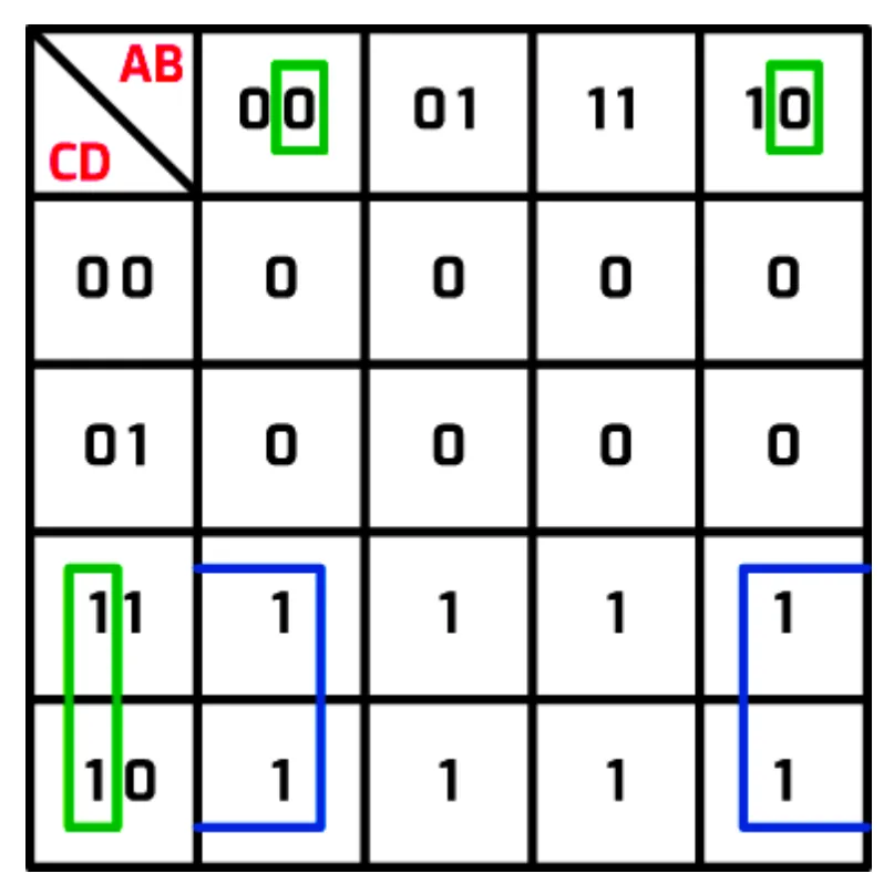
You can prove this by looking at the inputs: for every 1 in this group, B is always 0 and C is always 1. So the group represents C . NOT B.
Note In this map every cell in the bottom two rows holds 1, so in a full answer they would be circled as one group of eight (C) and this group of four would not be needed. The map is here to show how a group wraps round the edge.
Practise this: past-paper questions
- November 2021 · Paper 32 · Q7(b)(ii)Draw loop(s) around appropriate group(s) of 1s in the K-map to produce an optimal sum-of-products
- November 2022 · Paper 31 · Q7(b)Draw loop(s) around appropriate group(s) in the K-map to produce an optimal sum-of-products
- June 2023 · Paper 31 · Q7(b)Draw loop(s) around appropriate group(s) in the K-map to produce an optimal sum-of-products
- June 2023 · Paper 32 · Q9(c)Draw loop(s) around appropriate group(s) in the K-map to produce an optimal sum-of-products
Show 12 more
- June 2024 · Paper 31 · Q6(c)(ii)Draw loop(s) around appropriate group(s) in the K-map to produce an optimal sum-of-products
- June 2024 · Paper 32 · Q6(c)(ii)Draw loop(s) around appropriate group(s) in the K-map to produce an optimal sum-of-products
- November 2024 · Paper 31 · Q7(c)Draw loop(s) around appropriate group(s) in the K-map to produce an optimal sum-of-products
- November 2024 · Paper 32 · Q6(c)Draw loop(s) around appropriate group(s) in the K-map to produce an optimal sum-of-products
- June 2025 · Paper 31 · Q5(b)(ii)Draw loop(s) around appropriate group(s) in the K-map to produce an optimal sum-of-products
- June 2025 · Paper 33 · Q3(b)(ii)Draw loop(s) around appropriate group(s) in the K-map to produce an optimal sum-of-products
- November 2025 · Paper 31 · Q6(b)(ii)Draw loop(s) around appropriate group(s) in the K-map to produce an optimal sum-of-products
- November 2025 · Paper 32 · Q6(b)(ii)Draw loop(s) around appropriate group(s) in the K-map to produce an optimal sum-of-products
- November 2025 · Paper 33 · Q6(a)(i)Draw loop(s) around appropriate group(s) in the K-map to produce an optimal sum-of-products
- June 2026 · Paper 31 · Q6(c)(i)Draw loop(s) around appropriate group(s) in the K-map to produce an optimal sum-of-products
- June 2026 · Paper 32 · Q7(a)(ii)Draw loop(s) around appropriate group(s) in the K-map to produce an optimal sum-of-products
- June 2026 · Paper 33 · Q6(a)(i)Draw loop(s) around appropriate group(s) in the K-map to produce an optimal sum-of-products
Used later in
15.2 · 21 of 21Book page Contents
Multiple overlaps
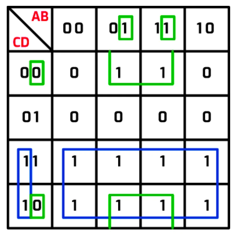
- The blue group of eight 1s represents C.
- The green group of four 1s wraps round the top and bottom edges, but it does not reach into the row where C = 1 and D = 1. If it did, it would be a group of six 1s, which is not allowed.
- The green group shows that the output is True when B = 1 and D = 0, so it represents B . NOT D.
This gives the full expression C + (B . NOT D).
Practise this: past-paper questions
- November 2021 · Paper 32 · Q7(b)(iii)Write the Boolean expression from your answer to part b(ii) as a simplified sum-of-products
- November 2022 · Paper 31 · Q7(c)Write the Boolean expression from your answer to part (b) as a simplified sum-of-products. Use Boolean algebra to give your answer in its simplest…
- June 2023 · Paper 31 · Q7(c)Write the Boolean logic expression from your answer to part (b) as a simplified sum-of-products. Z
- June 2023 · Paper 32 · Q9(d)Write the Boolean logic expression from your answer to part (c) as a simplified sum-of-products. Z
Show 12 more
- June 2024 · Paper 31 · Q6(c)(iii)Write the Boolean expression from your answer to part (c)(ii) as a simplified sum-of-products
- June 2024 · Paper 32 · Q6(c)(iii)Write the Boolean expression from your answer to part c(ii) as a simplified sum-of-products
- November 2024 · Paper 31 · Q7(d)(i)Write the Boolean logic expression from your answer to part (c) as the simplified sum-of-products. T
- November 2024 · Paper 32 · Q6(d)Write the Boolean logic expression from your answer to part (c) as the simplified sum-of-products. X
- June 2025 · Paper 31 · Q5(b)(iii)Write the Boolean logic expression from your answer to part (b)(ii) as the simplified sum-of-products
- June 2025 · Paper 33 · Q3(b)(iii)Write the Boolean logic expression from your answer to part (b)(ii) as the simplified sum-of-products. Z
- November 2025 · Paper 31 · Q6(b)(iii)Write the Boolean expression from your answer to part b(ii) as a simplified sum-of-products. Do not carry out any further simplification
- November 2025 · Paper 32 · Q6(b)(iii)Write the Boolean expression from your answer to part b(ii) as a simplified sum-of-products. Do not carry out any further simplification
- November 2025 · Paper 33 · Q6(a)(ii)Write the Boolean expression from your answer to part a(i) as a simplified sum-of-products. Do not carry out any further simplification
- June 2026 · Paper 31 · Q6(c)(ii)Write the Boolean expression from your answer to 6(c)(i) as a simplified sum-of-products. Do not carry out any further simplification
- June 2026 · Paper 32 · Q7(a)(iii)Write the Boolean expression from your answer to 7(a)(ii) as a simplified sum-of-products
- June 2026 · Paper 33 · Q6(a)(ii)Write the Boolean expression from your answer to 6(a)(i) as a simplified sum-of-products. Do not carry out any further simplification
15.2
Concepts in 15.2
Every idea explained in 15.2, and where else in the notes it is used.
| Concept | In one line | Also used in |
|---|---|---|
| absorption laws | A . (A + B) = A and A + (A . B) = A. | 15.2 Simplifying expressions with the laws |
| active-low input | An input that does its job when it is 0 rather than 1. | only here |
| associative laws | (A . B) . C = A . (B . C), and the same for +: the order of joining three inputs does not matter. | 15.2 Simplifying expressions with the laws |
| asynchronous circuit | A sequential circuit that processes its inputs as soon as they arrive. | 15.2 The SR flip-flop (NOR gates) |
| Boolean algebra | A formal way of writing logical statements, with symbols for AND, OR and NOT. | only here |
| Boolean identity | An equivalence that is true for every possible set of input values, used to simplify expressions. | 15.2 Boolean algebra, 15.2 Simplifying expressions with the laws |
| carry bit | The bit carried to the next column when an addition does not fit in one bit. | 15.2 The full adder, 15.2 The four-bit binary adder |
| carry-in | The carry passed into a column from the column before it. | 15.2 The four-bit binary adder |
| clock signal | A continuous stream of alternating 1s and 0s that keeps components in step. | 15.2 The SR flip-flop (NOR gates), 15.2 The SR flip-flop with NAND gates, 15.2 The JK flip-flop |
| clocked SR flip-flop | An SR flip-flop with a clock (enable) input, so it changes state only when the clock allows. | only here |
| combinational circuit | A circuit whose outputs depend only on its current inputs. | only here |
| commutative laws | A . B = B . A and A + B = B + A: the order of two inputs does not matter. | only here |
| cross-coupled gates | Two gates where the output of each is fed back as an input to the other. | 15.2 The SR flip-flop with NAND gates |
| De Morgan’s laws | NOT(A . B) = NOT A + NOT B and NOT(A + B) = NOT A . NOT B: split the bar and change the gate. | 15.2 Simplifying expressions with the laws |
| distributive laws | A . (B + C) = (A . B) + (A . C) and A + (B . C) = (A + B) . (A + C). | only here |
| dominance laws | 0 . A = 0 and 1 + A = 1. | 15.2 Simplifying expressions with the laws |
| double complement law | NOT NOT A = A: inverting twice gives the original value. | 15.2 Simplifying expressions with the laws |
| flip-flop | A sequential circuit that stores one bit, acting as a simple memory device. | 15.2 The SR flip-flop (NOR gates), 15.2 The SR flip-flop with NAND gates, 15.2 The JK flip-flop |
| four-bit binary adder | Full adders chained so the carry-out of each column feeds the carry-in of the next. | only here |
| full adder | A circuit that adds two bits and a carry-in, giving a sum and a carry-out. | 15.2 The four-bit binary adder |
| grouping 1s in a K-map | Loop horizontal or vertical groups of 1, 2, 4 or 8 cells, as large and as few as possible. | 15.2 Karnaugh maps and truth tables, 15.2 Reading the expression from a Karnaugh map, 15.2 Three-input Karnaugh maps |
| half adder | A circuit that adds two single bits, giving a sum (A XOR B) and a carry (A AND B). | 15.2 The full adder, 15.2 The four-bit binary adder |
| idempotence laws | A . A = A and A + A = A. | 15.2 Simplifying expressions with the laws |
| identity laws | 1 . A = A and 0 + A = A. | 15.2 Simplifying expressions with the laws |
| illegal state | An input combination that gives contradictory outputs, such as S = 1 and R = 1. | 15.2 The SR flip-flop with NAND gates, 15.2 The JK flip-flop |
| inverse laws | A . NOT A = 0 and A + NOT A = 1. | 15.2 Simplifying expressions with the laws |
| JK flip-flop | A clocked flip-flop with inputs J and K that can set, reset, hold or toggle. | only here |
| K-map order of input values | Headings go 00, 01, 11, 10 so that only one input changes from one cell to the next. | 15.2 Four-input Karnaugh maps |
| Karnaugh map (K-map) | A truth table laid out as a grid so that groups of 1s show how to simplify the expression. | 15.2 Drawing a Karnaugh map, 15.2 Worked example: a two-input map, 15.2 Reading the expression from a Karnaugh map, 15.2 Three-input Karnaugh maps, 15.2 Four-input Karnaugh maps, 15.2 Overlapping groups |
| overlapping groups | Groups in a K-map may share 1s, so a 1 can belong to more than one group. | only here |
| sequential circuit | A circuit whose outputs depend on the current inputs and on past inputs. | only here |
| SR flip-flop | A one-bit memory made of two cross-coupled NOR (or NAND) gates, with Set and Reset inputs. | 15.2 The SR flip-flop with NAND gates, 15.2 The JK flip-flop |
| sum of products | An expression made of AND terms joined by OR, such as A . B + NOT A . B. | only here |
| synchronous circuit | A sequential circuit whose operations are controlled by a clock. | only here |
| three-input gate | A gate with three inputs, so its truth table has 8 rows. | only here |
| wrap-around group | A K-map group that goes off one edge and continues on the opposite edge. | 15.2 Multiple overlaps |
Zain Merchant's notes, page by page, as printed in his book. The Notes tab has the same notes as text, with links.
Past-paper questions and mark schemes © Cambridge University Press & Assessment. Compiled for revision by Zain Merchant.
- June 2021 · Paper 31 · Q7Notes:The full adderGates with three inputsDrawing a Karnaugh map
- November 2021 · Paper 32 · Q7Notes:Boolean identities (the laws)Simplifying expressions with the lawsDrawing a Karnaugh mapReading the expression from a Karnaugh mapFour-input Karnaugh mapsOverlapping groupsGroups that wrap round the edgeMultiple overlaps
- June 2022 · Paper 32 · Q6Notes:The half adder
- November 2022 · Paper 31 · Q7Notes:Boolean identities (the laws)Simplifying expressions with the lawsDrawing a Karnaugh mapReading the expression from a Karnaugh mapFour-input Karnaugh mapsOverlapping groupsGroups that wrap round the edgeMultiple overlaps
- November 2022 · Paper 32 · Q8Notes:Sequential circuits and flip-flopsThe SR flip-flop (NOR gates)The SR flip-flop with NAND gatesBoolean identities (the laws)De Morgan’s lawsSimplifying expressions with the laws
- June 2023 · Paper 31 · Q7Notes:Boolean identities (the laws)Simplifying expressions with the lawsDrawing a Karnaugh mapReading the expression from a Karnaugh mapFour-input Karnaugh mapsOverlapping groupsGroups that wrap round the edgeMultiple overlaps
- June 2023 · Paper 32 · Q9Notes:Boolean identities (the laws)Simplifying expressions with the lawsDrawing a Karnaugh mapReading the expression from a Karnaugh mapFour-input Karnaugh mapsOverlapping groupsGroups that wrap round the edgeMultiple overlaps
- November 2023 · Paper 31 · Q6Notes:Gates with three inputsBoolean identities (the laws)Simplifying expressions with the laws
- November 2023 · Paper 32 · Q7Notes:Gates with three inputsBoolean identities (the laws)De Morgan’s lawsSimplifying expressions with the laws
- June 2024 · Paper 31 · Q6Notes:Gates with three inputsDrawing a Karnaugh mapReading the expression from a Karnaugh mapThree-input Karnaugh mapsOverlapping groupsGroups that wrap round the edgeMultiple overlaps
- June 2024 · Paper 32 · Q6Notes:Gates with three inputsDrawing a Karnaugh mapReading the expression from a Karnaugh mapThree-input Karnaugh mapsOverlapping groupsGroups that wrap round the edgeMultiple overlaps
- November 2024 · Paper 31 · Q7Notes:Boolean identities (the laws)Simplifying expressions with the lawsDrawing a Karnaugh mapReading the expression from a Karnaugh mapFour-input Karnaugh mapsOverlapping groupsGroups that wrap round the edgeMultiple overlaps
- November 2024 · Paper 32 · Q6Notes:Drawing a Karnaugh mapReading the expression from a Karnaugh mapFour-input Karnaugh mapsOverlapping groupsGroups that wrap round the edgeMultiple overlaps
- June 2025 · Paper 31 · Q5Notes:Drawing a Karnaugh mapReading the expression from a Karnaugh mapFour-input Karnaugh mapsOverlapping groupsGroups that wrap round the edgeMultiple overlaps
- June 2025 · Paper 32 · Q7Notes:Gates with three inputsBoolean identities (the laws)De Morgan’s lawsSimplifying expressions with the lawsDrawing a Karnaugh map
- June 2025 · Paper 33 · Q3Notes:Drawing a Karnaugh mapReading the expression from a Karnaugh mapFour-input Karnaugh mapsOverlapping groupsGroups that wrap round the edgeMultiple overlaps
- November 2025 · Paper 31 · Q6Notes:Gates with three inputsDrawing a Karnaugh mapReading the expression from a Karnaugh mapThree-input Karnaugh mapsOverlapping groupsGroups that wrap round the edgeMultiple overlaps
- November 2025 · Paper 32 · Q6Notes:Gates with three inputsDrawing a Karnaugh mapReading the expression from a Karnaugh mapThree-input Karnaugh mapsOverlapping groupsGroups that wrap round the edgeMultiple overlaps
- November 2025 · Paper 33 · Q6Notes:Boolean identities (the laws)De Morgan’s lawsSimplifying expressions with the lawsDrawing a Karnaugh mapReading the expression from a Karnaugh mapOverlapping groupsGroups that wrap round the edgeMultiple overlaps
- June 2026 · Paper 31 · Q6Notes:Gates with three inputsKarnaugh maps and truth tablesDrawing a Karnaugh mapReading the expression from a Karnaugh mapOverlapping groupsGroups that wrap round the edgeMultiple overlaps
- June 2026 · Paper 32 · Q7Notes:Boolean identities (the laws)De Morgan’s lawsSimplifying expressions with the lawsDrawing a Karnaugh mapReading the expression from a Karnaugh mapFour-input Karnaugh mapsOverlapping groupsGroups that wrap round the edgeMultiple overlaps
Past-paper questions and mark schemes © Cambridge University Press & Assessment. Compiled for revision by Zain Merchant.
Try the questions first.
Write your answers, then check them against the mark scheme. Your choice is remembered on this device.